CoRe+
TM
Installation Guide
16
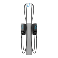
• Install the 2 provided terminal blocks (1 isolated
3-position terminal block for the live conductors,
and 1 non-isolated terminal block for the
grounding conductor) and the breakers onto the
mounting bracket with the provided screws.
• Connect the power supply cables from the top of
the terminal blocks to the breakers, depending
on the number of stations to be installed.
STEP 2:
Mounting bracket installation and power
supply cable connection:
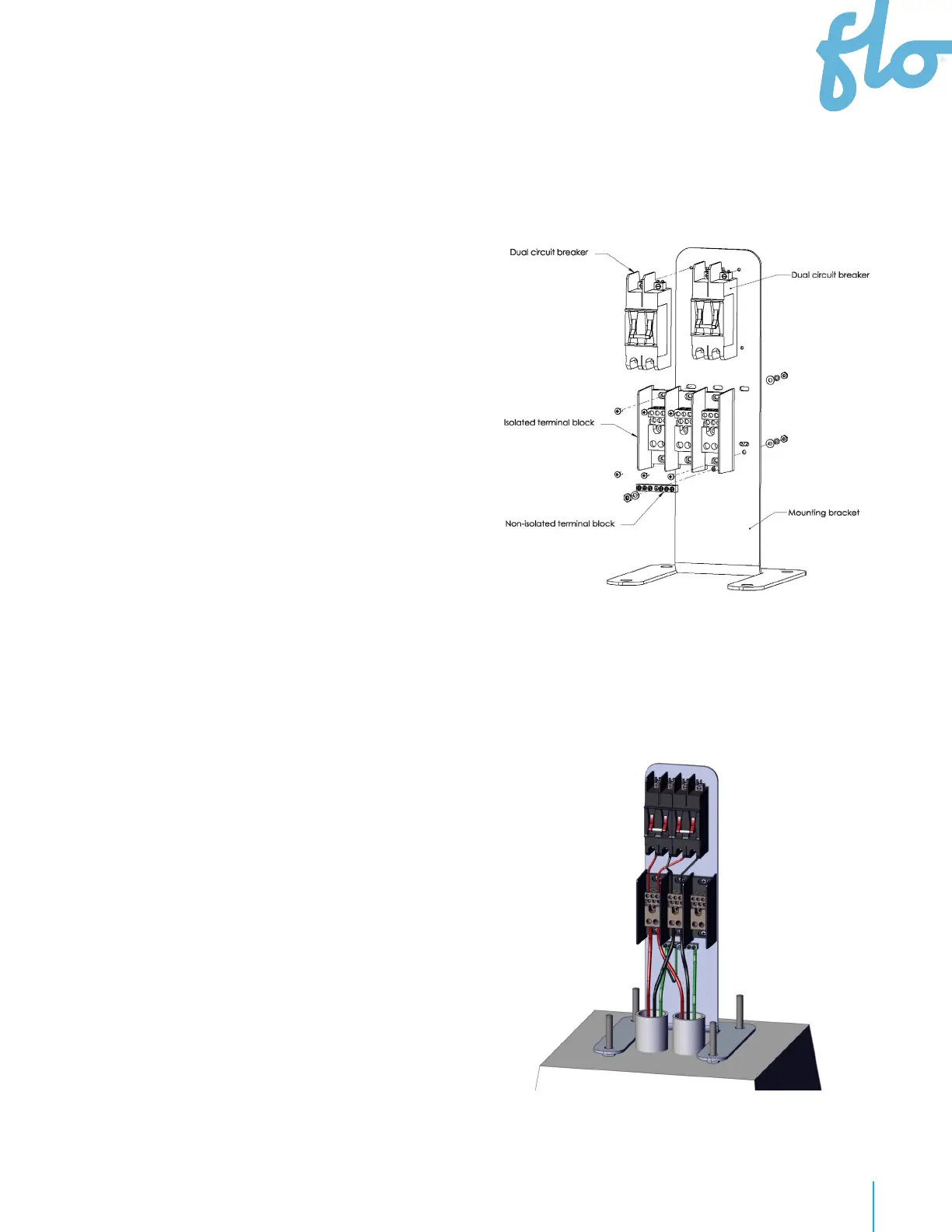
• Install the power supply cables coming from the
previous charging station and the power supply cables
going to the next one, letting 1 foot of cable protrude
from the conduit.
• Place the mounting bracket on the concrete base,
making sure that the anchor’s threaded rods pass
through the 4 holes in the base of the bracket.
• Connect the power supply cables to the bottom of the
terminal blocks.
Installation Guide Cascading
on a 150 A Circuit
STEP 1:
Mounting bracket pre-assembly
The pre-assembly requires the 150 A cascading kit
(FLO part number C+V1-PWCK-150/ACPE0007) and
1-pole or 40 A double pole circuit breaker (FLO part
number breaker-40D/ELBR007) depending on the
number of charging stations to be mounted on the
pedestal.