Do you have a question about the Flo CoRe+ Series and is the answer not in the manual?
Guidelines for installing the communication gateway, including placement and power.
Device compliance with Industry Canada licence-exempt RSS standards.
Equipment tested for Class A digital device compliance per FCC Rules.
Radiated power output below FCC limits for general population.
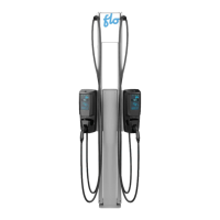
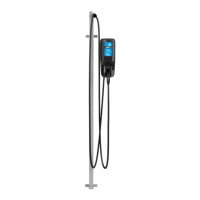
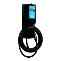
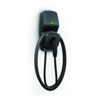
Details CoRe+V2, CoRe+VBV2, and CoRe+PSV2 models.
Power supply, output, temperature, weight, and standards.
Basic precautions for using electric products.
Circuit protection, conductor sizing, grounding, and cable strain relief.
Advice on handling sharp edges and specific usage warnings.
Provides overall dimensions and cable length for the charging station.
Attaching head base to wall/post using anchors and connecting cables.
Preparing equipment for back entry and connecting cables.
Aligning opening with wall box and connecting wires.
Connecting cables and installing the head to the base.
Steps for power-on observation, card authentication, and protection circuit test.
Connecting up to four stations to one circuit with a site controller for dynamic sharing.
Assembling the 40 A cascading kit, DIN rail, and terminal blocks.
Installing bracket on base and connecting power supply cables.
Sliding pedestal, securing nuts, passing wires, and connecting stations.
Assembling the 150 A kit, breakers, and terminal blocks.
Installing bracket on base and connecting power supply cables.
Sliding pedestal, securing nuts, passing wires, and connecting stations.
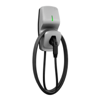
The FLO CoRe+™ is a Level 2 electric vehicle charging station designed for both residential and commercial applications. It offers a robust and user-friendly solution for charging electric vehicles, with various models available to suit different needs. The device is built for durability and outdoor use, featuring a 4X enclosure type, making it suitable for a wide range of environmental conditions.
The primary function of the FLO CoRe+™ is to provide Level 2 charging for electric vehicles equipped with a SAE-J1772 connector. It converts AC power from the grid into a form suitable for charging an EV's battery. The charging station is designed to be either ground-based, wall-mounted, or post-mounted, offering flexibility in installation.
The CoRe+™ series includes different models:
The charging station incorporates built-in protection against overvoltage conditions and leakage current to ground, ensuring safe operation. It requires a split-phase 120/240 VAC supply or a 3-phase 120/208 VAC supply, protected by a 40 A fuse or circuit breaker. The power supply must be grounded, and the connection requires two lines and one ground connection, with the neutral not being used.
For commercial applications, especially in California, the commissioning process might require an authorized Division of Measurement Standards (DMS) agent if the station is intended for energy billing.
The FLO CoRe+™ offers several features that enhance its usability:
The design of the FLO CoRe+™ emphasizes ease of installation and maintenance, with clear guidelines to ensure longevity and safe operation:
| Input Voltage | 100-240VAC |
|---|---|
| Output Voltage | 12V / 24V |
| Charging Current | 10A |
| Battery Type | AGM, GEL |
| Charging Stages | 8-stage charging |
| Protection | Overvoltage, short circuit, reverse polarity, overheat |
| Operating Temperature | -20°C to +50°C |