10
CHECK THE FOLLOWING TO ENSURE
PROPER OPERATION OF THE
ELECTRIC MOTOR DRIVE
Electrical System:
1. Power wires to the batteries & motor are
properly connected, corrosion free & tight.
2. Batteries are fully charged. When tested a 12 volt
battery will have between 12.7 and 13.8 volts.
3. Limit Switch is connected to 13-in. plug.
4. Wired Remote/Key Switch is connected to
10” plug.
5. Wireless Receiver (optional) is connected to
7” plug.
Important:
• Test the upper & lower limit switches before
initial use and seasonally to ensure the drive
motor shuts off automatically before coming
to a hard stop. Test by approaching the upper
& lower cradle positions cautiously with quick
on/off triggers of the remote.
• If any portion of the electrical system is
submerged, please refer to the owner’s
manual for corrective action.
Cable Note:
• Ensure that cradle travels freely to the bottom
of the lift and keeps tension on lifting cable at
all times.
120 VOLT AC WARNING
For the AC power
connection please
contact a licensed
electrical contra-
ctor to ensure a
safe connection.
You must have
120v/20amp
service to the
connection on
VSD drive train.
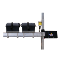
Keep the cables from the connection panel
inside the battery boxes by running them through
the rst box, and then into the second. The white
battery interconnect wire should also be neatly
contained within the battery boxes (Fig. 8).
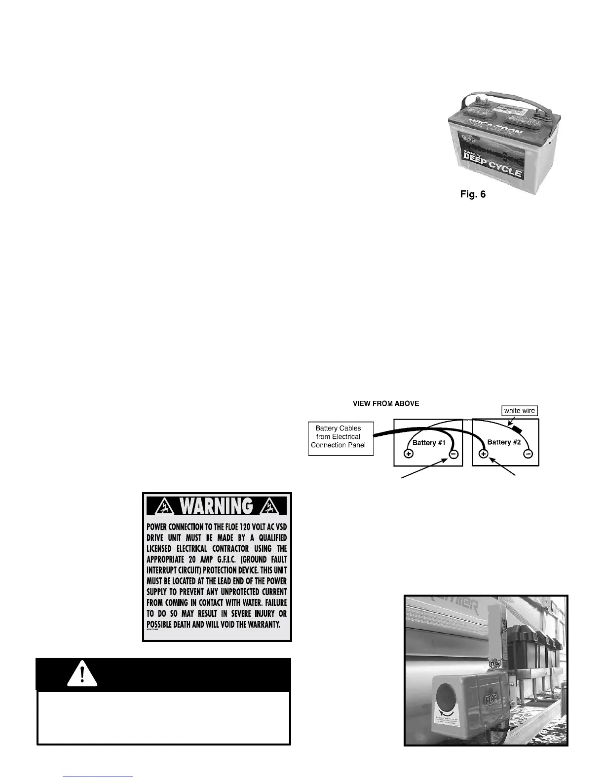
SELECTING THE BATTERIES
FOR 24-VOLT DC MODELS
Batteries are not included with the lift system. The
recommended bat-
teries (Fig. 6) are two
12-Volt, deep-cycle,
Group 27 (case size),
with 600 cold cranking
amps and stud post ter-
minals with wing nuts.
An Interstate SRM-27
meets this criteria.
CONNECTING THE BATTERIES
The DC lift comes standard with two battery trays
and plastic battery boxes, as well as the wiring
kit to connect them to the lift’s control panel. The
two 12-volt batteries connect together in series
to create a 24-volt system. It is important that
the two deep-cycle batteries are connected to
the cables leading from the electrical connection
panel exactly as shown in Fig. 7 below. This 24-
volt system will reduce the amperage draw on the
batteries, and maximize battery life.
Batteries that are improperly connected
can cause damage to the lift system,
the batteries, and a potential explosion.
WARNING
black ring connector
red ring connector
Fig. 7
24 Volt System
Fig. 8 Battery
Boxes & Trays
(Note how
cabling is neatly
stowed and
completely
contained within
the battery
boxes.)