15
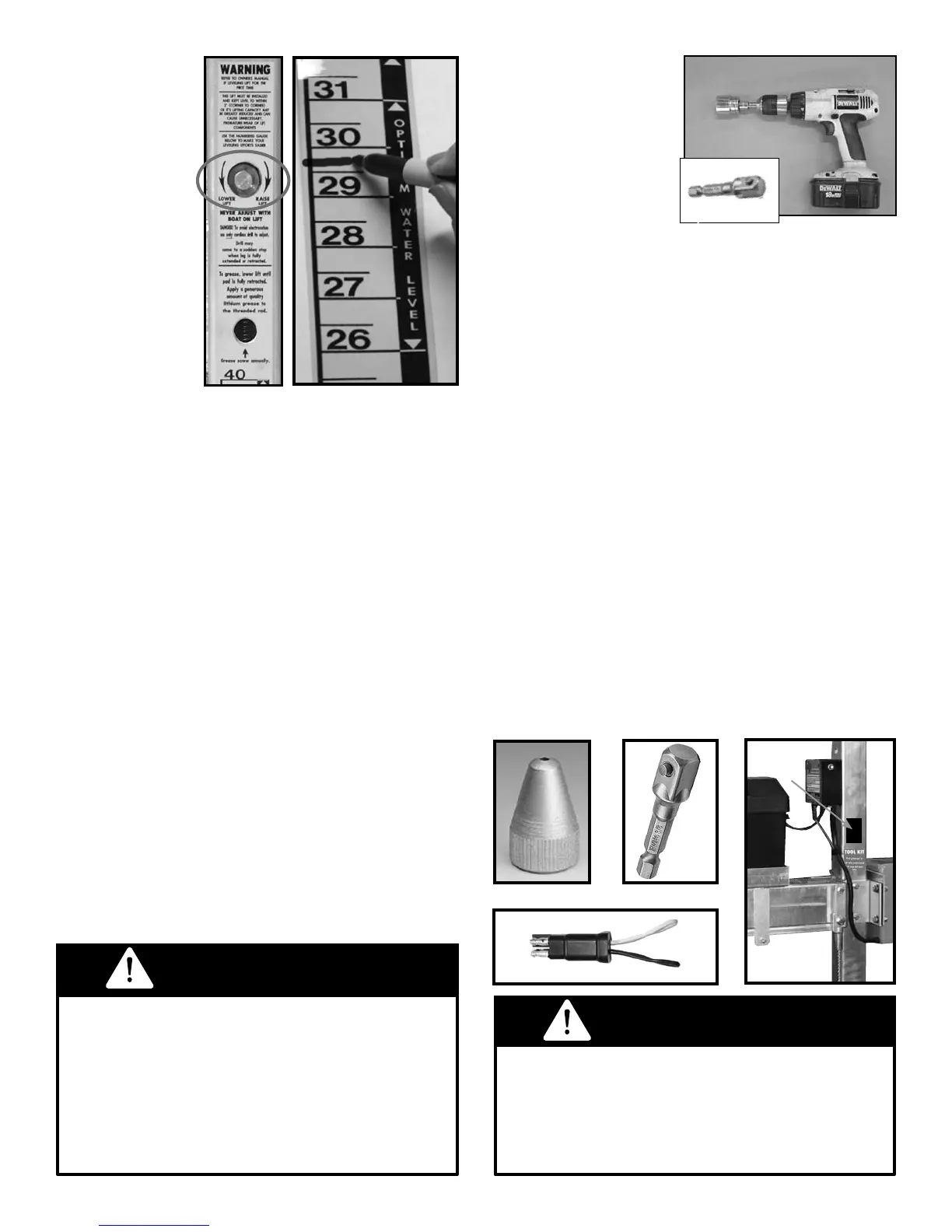
For leveling leg adjustment range, see boat lift
specications, page 8. The decal pictured in
Fig. 24 and 25 has a useful measuring tape so
that you can see the water level on each corner
post. It is important that the water level reads
the same on all four corner posts. Once you
determine what leg extension measurement
works best for your boat and lift, you can use
a waterproof marker to draw a line at that point
on the tape of one corner post. This will be very
helpful in following seasons, either for you or
especially for a hired installer who may be
unfamiliar with your boat, shoreline, and lift.
Fig. 27 Fig. 28
Fig. 29
Fig. 26
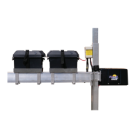
Cordless Drill with
Socket Attachment
The 3/8” drive socket
adapter bit shown in inset
photo, along with a 3/4”
socket, will allow you to
use a cordless drill on the
leveling nuts to lower or
raise the lift’s legs.
clockwise will
raise the lift;
counterclock-
wise will lower
it. Use a 3/4”
socket with a
socket wrench
or a 14 volt (or
larger) cordless
drill (Fig. 26) to
adjust. Each of
the four legs ad-
justs indepen-
dently so the lift
can be perfectly
leveled. As the
lift is raised or lowered, alternate among all four
legs after 1-1/2” to 2” of adjustment – similar to
tightening lug nuts on a tire rim. If the drill is work-
ing too hard, you are lifting too much on an indi-
vidual leg and need to proceed to the other legs.
Drill will come to a sudden stop when leg is
fully extended or retracted. When approaching
the end of the leg’s travel, reduce the
speed of the drill. This will prevent you from
twisting your wrist or accidentally dropping
the drill. Do not use an impact wrench to
adjust as this will cause damage to the lift.
WARNING
Fig. 24
Fig. 25
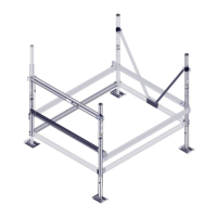
FLOE TOOL KIT
FLOE has provided a kit with four tools for use
with your VSD boat lift.
1. Flush Style Grease Gun Tip (Fig. 27)
(for greasing the ball-screw mechanism)
2. 3/8” Drive Socket Adapter Bit (Fig. 28)
3. Limit Switch Bypass Test Plug (Fig. 29)
(See VSD Diagnostics on page 29 for
instructions on how to use the bypass plug.)
The Velcro backed tool kit can be attached to the
lift frame, so that these tools are readily available
when needed. The kit is made from solution dyed
polyester and has a fold-over ap to help protect
these adapters from the elements.
To attach the tool kit:
Remove the adhesive protective paper from the
back of the vinyl pouch and place the tool kit on
the corner post as shown, see Fig. 30. Now the
tools will be easy for you or an installer to locate.
WARNING
Never adjust leveling legs (up or down)
with a boat on the lift. The added weight
of the boat will apply extreme pressure to
the adjustment system causing potential
mechanical failure and/or serious bodily injury.
Place tool
kit here
Fig. 30