7
Replacing Internal Parts
1. Remove the turbine from the sys-
tem as detailed above.
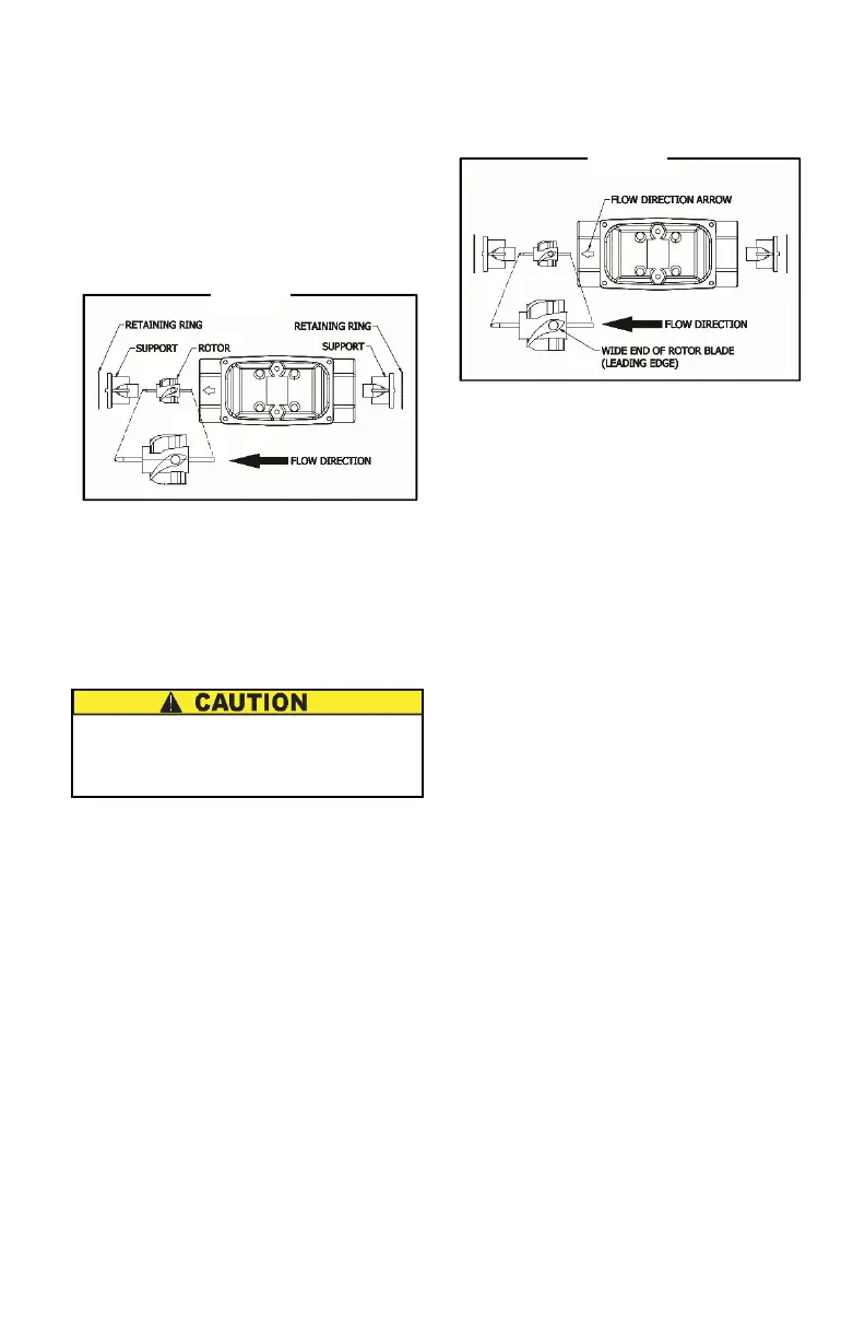
Note: Carefully notice the orientation of
all internal parts as they are re-
moved, especially the orientation
of the rotor to the flow direction
arrow. See Figure 2.
2. Using a small tool such as a screw-
driver or awl, gently pry one retain-
ing ring from its groove. Remove
the support. If necessary, use nee-
dle nose pliers. Little or no force
should be required.
3. Carefully remove the rotor.
Handle the rotor carefully. Even
small scratches or nicks can affect
accuracy.
4. Turn the turbine over and remove
the other retaining ring. Remove
the other support.
5. Clean, as detailed below, or discard
as necessary.
6. Replace one support and retaining
ring. Parts should drop easily into
place with little or no force.
7. Install the rotor. Make sure the wide
end of the rotor’s blades faces the
flow direction. See Figure 3.
8. Turn the turbine over and drop the
second support into place. Put the
final retaining ring into position.
9. Reinstall the turbine, purge the sys-
tem of air, and verify accuracy be-
fore use.