Calibration of the analog output signal is performed using the
display menu, a HART handheld communicator, the
ValveSight DTM or the LCD menu.
The AO does not interfere with positioner operation.
The AO signal corresponds with the configuration of the Signal
At Closed DIP switch setting. If the valve closes with a four mA
signal, the AO will show a four mA signal when closed. If the
valve closes with a 20 mA signal, the AO will show a 20 mA
signal when closed. This can be changed with an AO
calibration.
CAUTION: Proper ESD precautions must be observed
during AO connection to a power supply or loop calibrator to
avoid possible personal injury and property damage in the
case of an over-voltage incident. Perform the following
precautions prior to connecting the AO to power: ground the
positioner, ground the power supply source and ground the
technician performing the connection.
NOTE: The AO has an internal fuse. In the event of a surge
this fuse could be damaged and leave the AO nonfunctional.
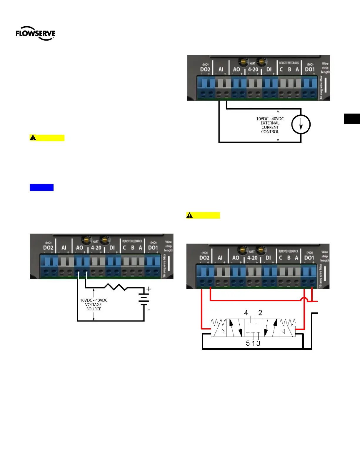
For AO function connect AO terminals in series with a 10 to 40
VDC power supply, including a method to determine the
current. The AO current will follow the valve position and will
have a range of 4-20mA. See Figure 17 for more info.
Figure 16: Analog Output Circuit
6.3.2 Auxiliary Analog Input
The AI circuit requires that the current loop system allows for
a 10 VDC drop across the positioner at maximum loop current.
The current operating range is from 4 to 20 mA. See Figure 8
for more details.
Figure 17: Auxiliary Analog Input Circuit
6.3.3 Discrete Output 1 and 2
DO1 and DO2 are both normally open outputs and are
exclusively used to control a 4-Way solenoid-controlled valve
block which drives the actuator. See Figure 9 for connection
detail.
CAUTION: There is a maximum 24VDC at 400mA rating
for the DO output circuits. Exceeding these limits will damage
the outputs. 4-Way valve 24V solenoid current consumption
must be less that the output rating.
Figure 18: Discrete Output 1 and 2 Solenoid
connection
 Loading...
