Logix™ 3800zb Digital Positioner FCD AIIOM001030_EN 02/23
flowserve.com 18
6.3.4 Discrete Input
Use the Discrete Input to signal the positioner to begin a partial
stroke test, or move to a predefined position as long as the
signal remains.
Supply a low voltage (or no voltage) to indicate a normal state.
Raise the voltage to indicate the tripped state.
The configuration of the discrete output signal is done using
the display menu, a HART handheld Communicator, or the
ValveSight DTM.
CAUTION: During the use of the Discrete Input function,
the valve may stroke unexpectedly. Follow internal
procedures, ensuring that the configured movement of the
valve (performing a PST or moving to a set-point) is allowed.
Notify proper personnel that the valve will stroke, and make
sure the valve is properly isolated if required.
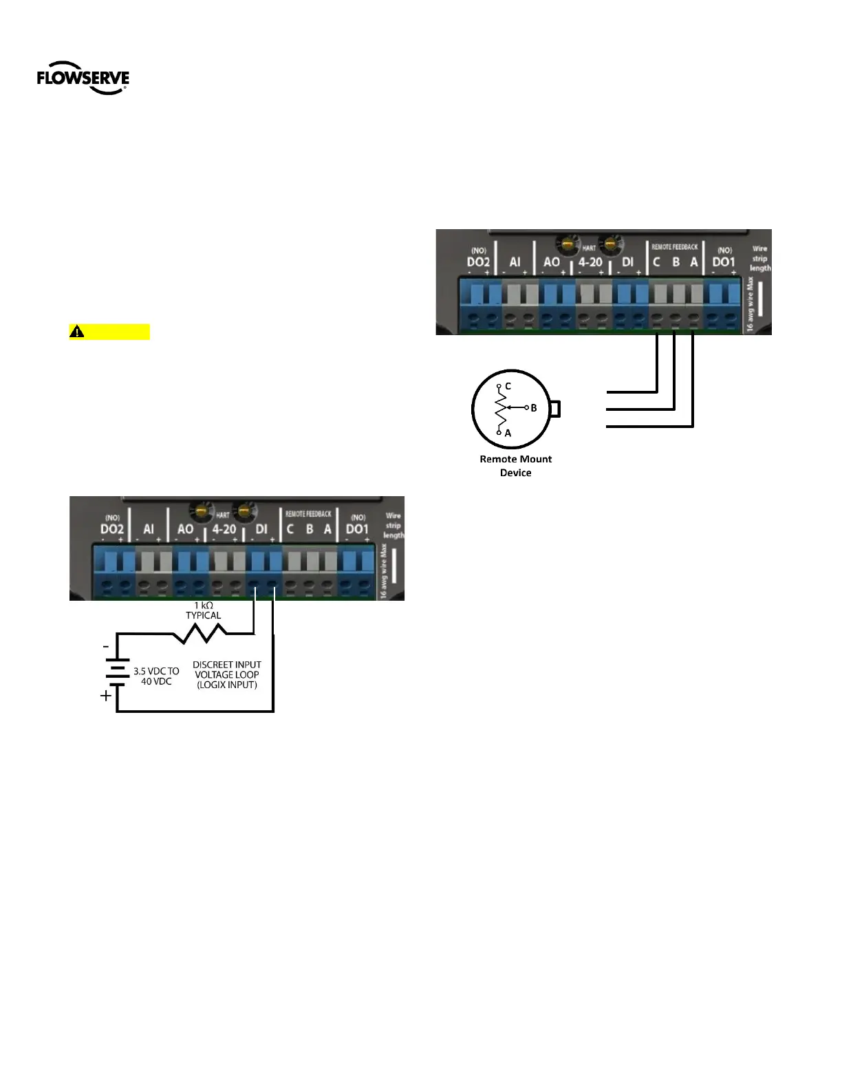
For the DI function, wire the DI terminals in series with a 3.5
to 40 VDC power supply as shown in Figure 20. Keep the
voltage low under normal circumstances. Raise the voltage
to create a tripped input state.
Figure 19: Discrete Input Circuit
6.3.5 Remote Mount
Use the remote mount option where excessive vibration or
environmental factors prevent the placement of a positioner
directly on the valve. The remote mount is an integrated part
of the Logix 3800zb circuitry. Wire the remote mount with
Black to terminal C, White to terminal B, and Red to terminal
A. For HART units, maximum cable length should be less than
30.5m (100ft). See
Figure 20 for remote mount connections.
See section 15.5 Remote Mount Specifications for additional
specifications.
Figure 20: Remote Mount Circuit (HART)
 Loading...
