61
Logix
®
520MD+ and 510+ Digital Positioners FCD LGENIM0105-15-AQ – 05/16
flowserve.com
18.7 Replacing a Main Board
Removal
1. Make sure the valve is bypassed or in a safe condition.
2. Remove the outer cover.
3. Disconnect the power to the positioner.
4. Remove the inner cover. See Figure 48: Inner Cover above.
5. Disconnect the power cable to the main board.
6. Disconnect the auxiliary card cable if present. See Figure 50:
Auxiliary Card on page 60.
7. Disassemble the switch mechanism if present.
8. Remove the inner cover by removing the 6 retaining screws. See
Figure 48: Inner Cover.
9. Remove the screws from the main circuit board. See Figure 51:
Main Board Screws.
10. Gently lift the main board rotating the bottom up while keeping
the top in place.
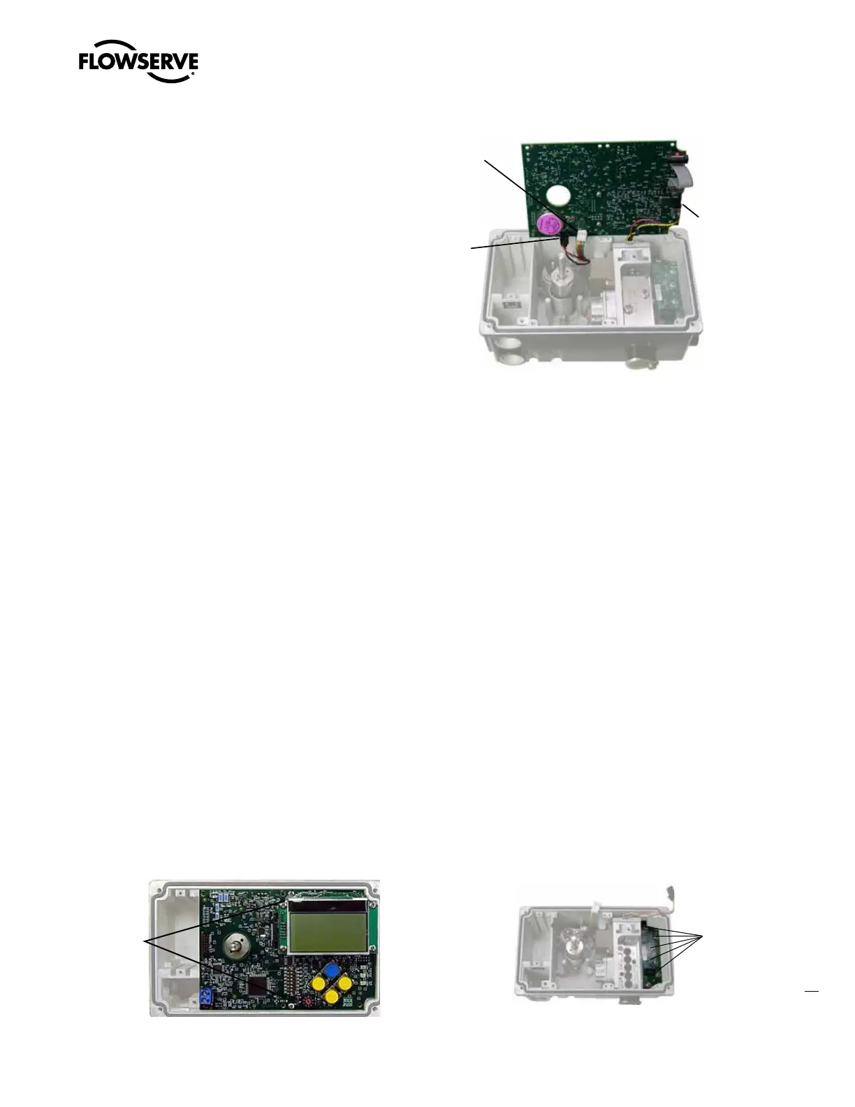
11. Disconnect the pressure sensor board cable, the hall sensor
cable, the piezo cable and the feedback cable. (Use a small flat
screwdriver to pry the locking features and carefully separate the
connector from the main board. Be careful not to pull the cable,
as this may cause damage to the cable.) See Figure 52.
Installation
1. Place the main board on the positioner base with the 4-20 mA
input on the same side as the electronic access ports.
2. Lift the main board rotating the bottom (configuration switches)
upwards while keeping the top in place.
3. Connect the pressure sensor board cable, the hall sensor cable, and
the feedback cable. Ensure the connector’s locking features engage.
4. Place the main board on the positioner base, ensuring the cables
are clear of the feedback gears. Insert the two retaining screws.
5. Replace the inner cover by inserting the 6 retaining screws.
6. Calibrate.
Figure 51: Main Board Screws
Hall
Sensor
Connector
Piezo
Connector
Feedback
Pot
Connector
Figure 52: Main Board Connectors
18.8 Replacing the Pressure Sensor Board
Removal
1. Remove the main board. See procedure above. (Disconnecting
the hall sensor and feedback cables is not required.)
2. Unscrew the 6 screws holding the pressure sensor board in
place. See Figure 53.
3. Remove the pressure sensor board.
Installation
1. Place the pressure sensor O-rings in the three holes.
2. Cover the O-rings with the pressure sensor board.
3. Insert the 6 screws. Tighten until the pressure sensor board
makes firm contact with the base.
Calibration
1. Initiate a Pressure or Triple Calibration from the LCD or DTM.
2. To calibrate the supply pressure sensor 0 value, disconnect the
supply air. Go to Edit Variables. Write the value from variable 74
(PS ADC Count) to variable 71. (PS ADC Count at 0 psi). Recon-
nect the supply air.
3. To keep the calibration values even after a Factory Reset, write a
1 to Variable 104.
Figure 53: Pressure Sensor Board
Main
Board
Screws
Pressure
Sensor
Screws