EP5 Electro Pneumatic Digital Positioner FCD PMENIM0006-00-A5 12/18
14
8. Indicator adjustment
P5/EP5: To adjust the indicator, take off front cover and pull the indicator upwards until it comes off
the Allen screw.
Before installing the indicator make sure that the Allen screw is tightened. Press the indicator on the
screw and adjust it by rotating clockwise to desired position.
P4: Loose screw, adjust indicator, tighten screw.
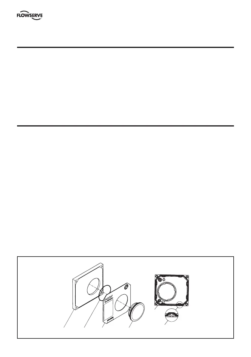
9. Front cover and indicator cover
The front cover of P5 is secured to the pneumatic unit with four captured screws and sealed with an
O-ring 1. The O-ring can be looped over notches 2 in the front cover to allow for drainage. There are
eight locations on the front cover where the O-ring can be looped. This O-ring system is common
to the Pneumatic unit , I/P unit and Feedback unit in the PMV Valve Control System P5. This unique
sealing system allows for complete sealing or draining of the units by changing the position of the
O-ring.
The indicator cover 3 is O-ring sealed and secured by a bayonet coupling. The indicator cover is
also used to secure the identification cover 4.
To remove the indicator cover turn it slightly counterclockwise until it loosens. Identification cover
and O-ring 5 are now removable.
When installing indicator cover and identification cover make sure that the O-ring is properly
engaged.
4315
2
1