EP5 Electro Pneumatic Digital Positioner FCD PMENIM0006-00-A5 12/18
16
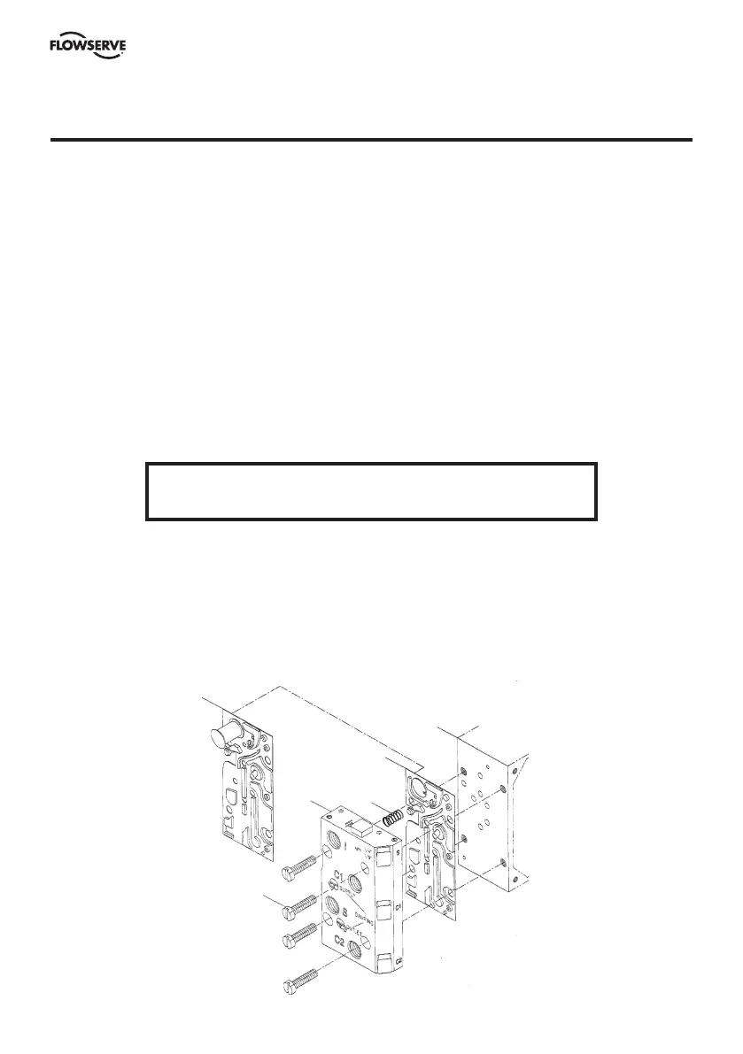
11. How to mount the I/P Unit to the positioner unit (P5/EP5)
Switch off supply air and disconnect input signal – port I.
Loosen screws 3 and remove connection block 1, the gauge or plug from port Ip, the fitting from
port I and existing gasket 4. Carefully install gasket 6 supplied together with I/P unit. When correct
installed port I will be blocked by the gasket.
Make sure that relief valve spring 5 is installed properly. Install the connection block 1 to the
positioner unit 2.
Remove cover on I/P unit.
Install the I/P unit to the top of the Positioner unit, making sure that the four O-rings are present
and properly seated. Tighten the unit with the three screws. (See fig. 1 and 2 page 16) Screw 1 first,
screw 2 last.
Connect input signal cable to port I
E
and tighten the cable gland (see fig 5 on page 16). Adjust the
O-ring on the I/P Unit housing to desired position - sealed or drained. (See fig 3 on page 16 or
section 9 on page 14).
A gauge indicating output signal from the I/P converter can be installed in port P. Make sure that the
filter plug is tightened before supply air is switched on (Fig 4 on page 16).
WARNING!
Units installed in hazardous areas must have proper approvals.
2
4
5
1
3
6