EP5 Electro Pneumatic Digital Positioner FCD PMENIM0006-00-A5 12/18
19
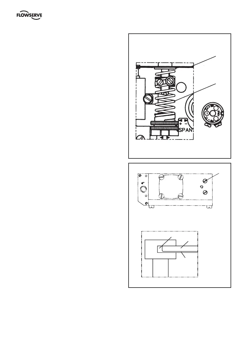
Feedback spring
Once the front cover and indicator are removed,
the feedback spring can be easily accessed.
Hold the spring 1 from the top, pull down and
out.
When installing, hold the assembly at the top,
guide the lower part to position on the zero
screw, then press down until it fits easily under
the balance arm 2. Make sure that the assembly
is aligned properly against the lower arm and
the notch is engaged in the tab on the balance
arm 2.
Balance arm
The balance arm 3 can only be removed after
I/P unit, diaphragm and feedback spring have
been removed. (See sections above and on
page 16, 18 and 19).
Loosen the screws 3 and the balance arm can
be removed.
When installing the balance arm make sure
that the leafspring 4 on the underside of the
balance arm 5 is properly engaged into the
groove 6 of the spool in the pilot valve. Tighten
the two screws 3 holding the balance arm to the
positioner.
1
2
3
6
5
4