HF110PEN_v0501_04
Page 37
Ci = 17nF
910
11
Common ground
Common ground
Common ground
Signal
TOTAL OF ALL CONNECTED
PPARATUS MAY NOT EXCEED
MINUS 17nF
(17nF IS USED BY THE ANALOG
OUTPUT SIGNAL TERMINAL 7+ 8)
Co
66nF
Supply *
Main supply
Circuit depends on
type of signal
Power supply type PD: 16-30V DC
(please note: PD battery supply (type PC) is NOT allowed in IIC applications).and
Flowmeter input
type: P
pulse
nalog output type AP:
passive 4-20mA
5
6
Common ground
0
1
27
8
123456
e.g. counter
e.g. indicator
TERMINAL CONNECTORS
F100-series
HAZARDOUS AREA
reset total
Status input type IB:
Ci is negligibly
small
12
13
Common ground
RXD
Common ground
TXD
28
26 29
DTR
+12V
27
+ 3.2V
low-pass
filter
1M
Modbus communication type CT: TTL
Please note: communciation type CT is allowed in IIC applications.not
* Note power supply type PD: the supply voltage to the sensor is maximum 8.7V (Uo=8.7V Io=25mA Po=150mW)
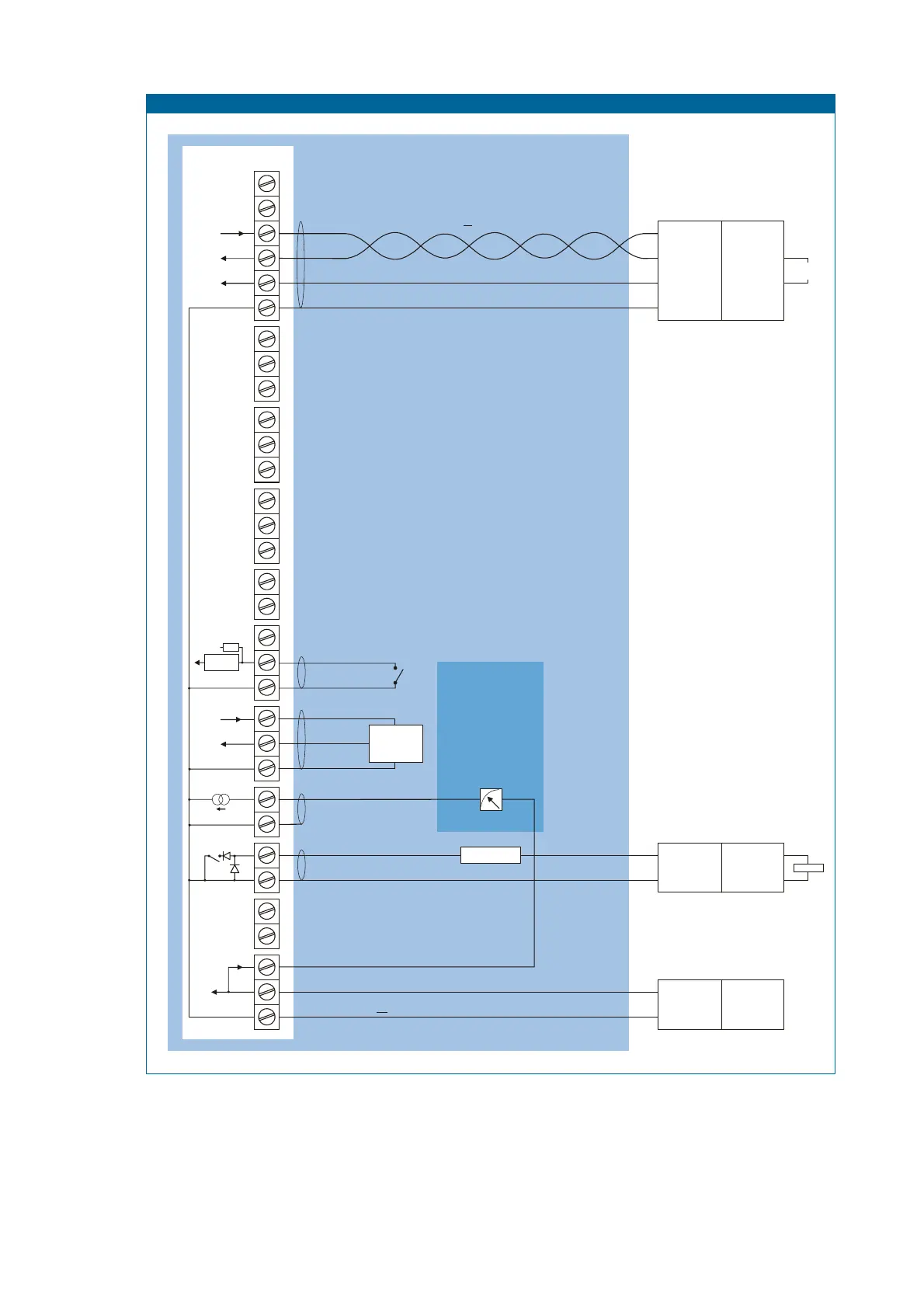
Configuration example IIB/IIIC and IIC - F110-P-AP-IB-(CT)-OT-PD-XI
Pulse output type OT:
passive transistor
Ci is negligibly
small
Ci is negligibly
small
e.g. PC
Note: above values are safety values.
Consult the technical specification for operational values.
e.g. counter
123456
SAFE AREA
Isolator
TTL to:
RS232
RS422
TTL
For example:
MTL5051
I.S. Certified
+
-
+
-
Power supply or
switch interface
For example
MTL5525
MTL5511
= max. 30 V
= max. 100 mA
= max. 0.75 W
Uo
Io
Po
= max. 30 V
= max. 250 mA
= max. 0.85 W
Uo
Io
Po
+
-
Power supply
For example
MTL5525
Uo
Io
Po
= max. 30 V
= max. 100 mA
= max. 0.75 W
* Note: Communication only allowed when configured as IIB/IIIC.
Fig. 15: Configuration example 2 Intrinsically Safe.