HF115PEN_v0501_04
Page 35
Explanation Intrinsically Safe options:
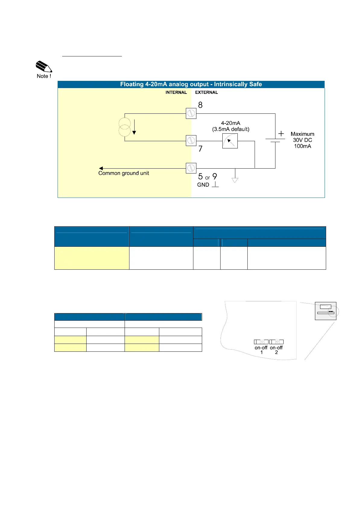
Type AF - Intrinsically Safe floating 4-20mA analog output:
A floating 4-20mA signal proportional to the flowrate is available with this option. When the output is
disabled, a 3.5mA signal will be generated. Max. driving capacity 1000 Ohm @ 30V DC.
Note! It is required to link the minus from the analog output - terminal 7 - with a ground terminal of
the unit; terminal: GND, 3, 5, 9, 12 or 15.
Type PD - Intrinsically Safe power supply and sensor supply - Terminal GND- 01 and 11.
TYPE SENSOR SUPPLY
Terminal
GND 01 02
PD
Input voltage:
8-30V DC
3,2 - 8,1V L- L+
output voltage is according
the input voltage; internally
linked with terminal 01.
Terminal 02: this terminal offers the same voltage as connected to terminal 01.
Terminal 11: this terminal offers a 3.2V or 8.1V to power the sensor.
This voltage is selected with the switch(es) inside the enclosure. First, remove the terminals after
which the internal plastic cover can be removed.
Switch position Switch position
terminal 11 terminal 14
SWITCH 1 VOLTAGE SWITCH 1 VOLTAGE
on 8.1 V DC on 8.1 V DC
off 3.2 V DC off 3.2 V DC
Fig. 13: Switch position voltage selection type PD-XI.

 Loading...


