True-rms Multimeter
Calibration Adjustment
17
Note
Set the calibrator to Standby before you change the function switch position
and after you complete adjustment of each function.
If the calibration adjustment procedure is not properly completed, the Meter
will not operate correctly.
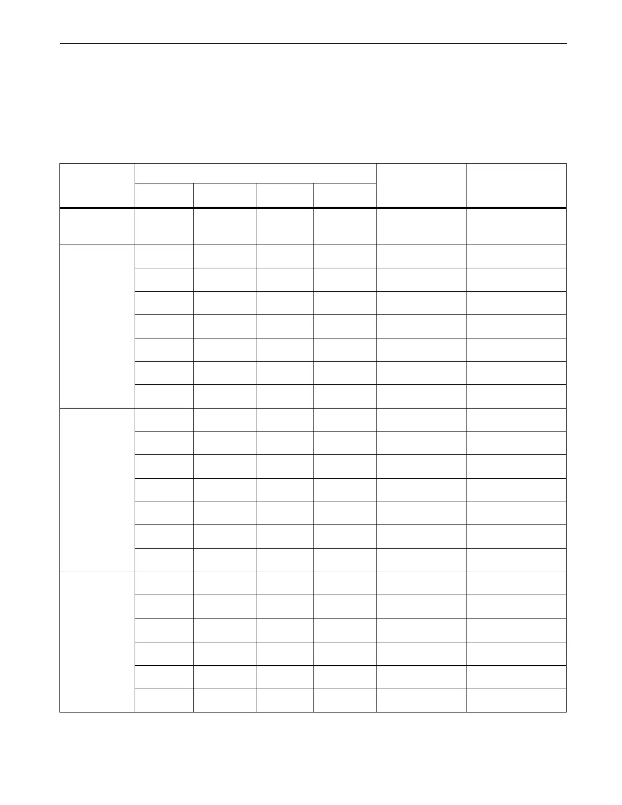
Table 5. Calibration Adjustment Steps (110/114/115/116/117)
Rotary
Switch
Position
Display Reading
Input
Terminals
Calibrator
Source Value
110/114
115
[1]
116
[1]
117
[1, 2]
Ω
Ohms
NA
C001
C001
C001
[2]
no leads no leads
m
C001 C002 C002 C002
VΩ/+ and COM 0 V, 0 Hz
C002 C003 C003 C003
VΩ/+ and COM 300 mV, 0 Hz
C003 C004 C004 C004
VΩ/+ and COM 100 mV, 0 Hz
C004 C005 C005 C005
VΩ/+ and COM -300 mV, 0 Hz
C005 C006 C006 C006
VΩ/+ and COM 60 mV, 0 Hz
C006 C007 C007 C007
VΩ/+ and COM 600 mV, 0 Hz
C007 C008
C008 C008
VΩ/+ and COM 600 MV, 60 Hz
Ω
Ohms
C008 C009 C009 C009
VΩ/+ and COM 600 Ω, 2-wire comp
C009 C010 C010 C010
VΩ/+ and COM 6 kΩ
C010 C011 C011 C011
VΩ/+ and COM 60 kΩ
C011 C012 C012 C012
VΩ/+ and COM 600 kΩ
C012 C013 C013 C013
VΩ/+ and COM 6 MΩ
[3]
C013 C014 C014 C014
VΩ/+ and COM short
[3]
C014 C015
C015 C015
VΩ/+ and COM 40 MΩ
[3]
C015 C016 C016 C016
VΩ/+ and COM 6 V, 60 Hz
C016 C017 C017 C017
VΩ/+ and COM 60 V, 60 Hz
C017 C018 C018 C018
VΩ/+ and COM 600 V, 60 Hz
C018 C019 C019 C019
VΩ/+ and COM 6 V, 0 Hz
C019 C020 C020 C020
VΩ/+ and COM 60 V, 0 Hz
C020 C021
C021 C021
VΩ/+ and COM 600 V, 0Hz
 Loading...