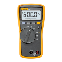
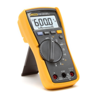
110/113/114/115/116/117
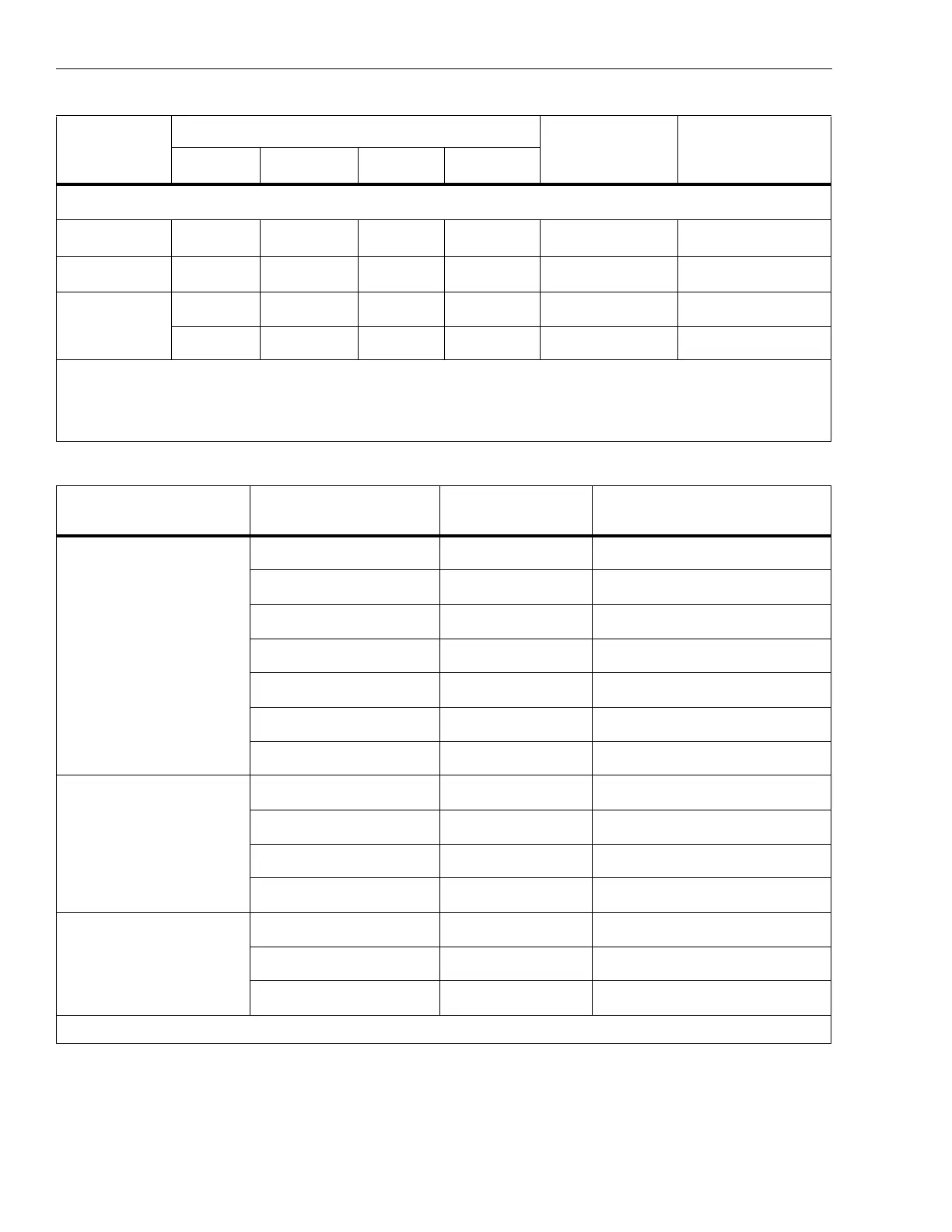
Calibration Information
18
Table 6. Calibration Adjustment Steps (113)
Set calibrator to standby, reconfigure leads, and program for amps output.
NA
C022
NA
C022
A and COM 6 A, 60 Hz
[3]
NA
C023
NA
C023
A and COM 6 A, 0 Hz
$
DC μAmps
NA NA C022 NA + and COM 600 μA, 60 Hz
NA NA
C023 NA + and COM 600 μA, 0 Hz
[1] Models listed in this column also refer to the “C” version of the model. For example, model 115 steps are valid for the 115C.
[2] Do not calibrate the 117 or 117C with a line-frequency power source nearby (for example, fluorescent light or power strip). These
devices can produce errors in the VoltAlert calibration.
[3] Wait an additional 5 seconds after calibrator has settled before pressing g.
Rotary Switch
Position
Calibration Steps Input Terminals Calibrator Source Value
k CHEK
mV ac/dc
C/01 + and COM 0 V, 0 Hz
C/02 + and COM 300 mV, 0 Hz
C/03 + and COM 100 mV, 0 Hz
C/04 + and COM -300 mV, 0 Hz
C/05 + and COM 60 mV, 0 Hz
C/06 + and COM 600 mV, 0 Hz
C/07 + and COM 600 mV, 60 Hz
Ω
Ohms
C/08 + and COM 600 e, 2-wire comp
C/09 + and COM 6 ke
C/10 + and COM 60 ke
C/11 + and COM 600 ke
k CHEK
V ac
C/12 + and COM 6 V, 60 Hz
C/13 + and COM 60 V, 60 Hz
C/14 + and COM 600 V, 60 Hz
[1]
[1] To keep from tripping the calibrator to standby, ramp up the voltage in 50 V increments with a 5 second delay between increments.
Table 5. Calibration Adjustment Steps (110/114/115/116/117) (cont.)
Rotary
Switch
Position
Display Reading
Input
Terminals
Calibrator
Source Value
110/114
115
[1]
116
[1]
117
[1, 2]
 Loading...