150X Series
Calibration Manual
24
Table 10. Calibration Adjustment Steps
Switch Position Input Terminal Adjustment Step Input Value
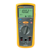
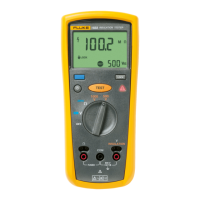
1000 V Insulation
+ : COM
− : A gnd (remote test
probe pin)
C-01 0 mA, 0 Hz
C-02 15 μA, 0 Hz
C-03 20 μA, 0 Hz
C-04 1.8 mA, 0 Hz
Continuity
C-05 0.5 mA, 0 Hz
C-06 5.0 mA, 0 Hz
C-07 0.5 mA, 0 Hz
C-08 5.0 mA, 0 Hz
C-09
5.0 mA, 0 Hz
[2]
C-10
300 mA, 0 Hz
[2]
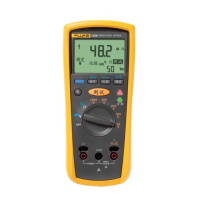
Volts
+ : Volts Input
− : COM
C-11 25.0 V, 0 Hz
C-12 750 V, 0 Hz
Continuity
+ : Continuity Input
− : COM
C-13 0.5 V, 0 Hz
C-14 5.0 V, 0 Hz
1000 V Insulation None C-15
Continuity
+: Continuity Input
−: COM
C-16
2.00 Ω (Use external
resistor, 0.1 %, 1 W,
50 PPM)
[1]
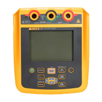
Any
+: Battery + Terminal
−: Battery − Te r m i n a l
C-18 + 5 V
[1] Must certify that this resistor is within 1.998 Ω to 2.002 Ω. This resistor should be mounted directly to the
Te s t e r Ω and COM terminals to minimize lead resistance.
[2] Wait at least 40 seconds before hitting the TEST button.
 Loading...