1550C/1555
Calibration Manual
12
Voltage Measurement Accuracy
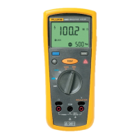
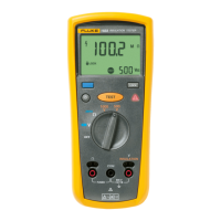
To verify voltage measurement accuracy of the Live Circuit Warning function, apply the
voltages listed in Table 6 to the + and - terminals of the UUT. Verify that:
• The UUT reading is within the display limits of Table 6.
• The UUT is beeping at a 1-second interval.
• is flashing on the display.
Table 6. Voltage Measurement Test
UUT Display Limits
Step
Voltage Source
Output
UUT Display UUT Tone
Minimum Maximum
1 -34 Vdc Flashing Hazard Beeps 29 V 39 V
2 240 Vac, 60 Hz Flashing Hazard Beeps 204 V 276 V
Adjustment Procedure
The product should be performance tested yearly to ensure compliance with its
specifications. When required, use the following adjustment procedure to bring the UUT
within its nominal accuracy specifications.
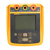
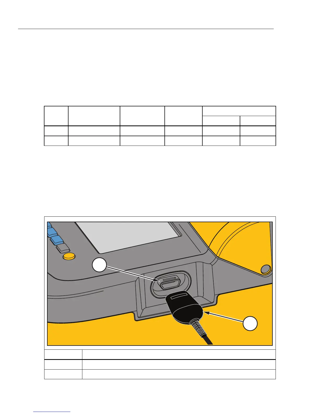
Interface Connection
Perform adjustment with software using a computer and IR (infrared) adapter.
Connect the Infrared Cable Assembly to the UUT IR Port and COM port of the computer.
Refer to Figure 3.
1
2
ghh04.eps
Item Description
IR Port
IR Device
Figure 3. IR Port

 Loading...