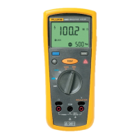
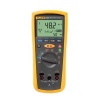
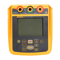
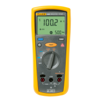
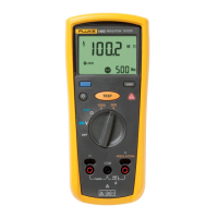
Insulation Tester
Adjustment Procedure
13
Instrument Setup
Turn the product on and wait for Test Voltage to appear on the display. From the
computer terminal, activate the Snorre program from the Windows Start menu. On the
Setup tab, confirm the selected COM port settings.
Warning
To prevent possible electrical shock, fire, or personal injury, do
not contact the output terminals or test equipment terminals
while performing the following procedures. There are
potentially dangerous voltages when the UUT is in the
"Calibrate HV Output and Measurement" mode.
Normalizing the HV Probe and Digital Multimeter
1. Connect the HV probe and digital multimeter to the 5520A NORMAL output
terminals, observing polarity. Manually set the multimeter for a range that has a
10 MΩ input impedance (e.g., 100 V) and provides a maximum resolution for a
500 mV and 5000 mV input.
2. Set the 5520A output to 506 V and note the digital multimeter reading. Record this
value.
3. Set the 5520A output to 1000 V and note the voltmeter reading. If the error is
> 0.025 % from the nominal value, convert the error from nominal to percentage.
Multiply 5005 V by this percentage and algebraically add to 5005 V. Record this
value.
4. Set the 5520A to standby and disconnect the HV probe and digital multimeter.
HV Adjustment
1. Select the CAL HV tab.
2. Connect the HV probe and digital multimeter to the output terminals of the UUT, as
shown in the connection diagram.
3. Press the START button to begin adjustment. The UUT briefly displays HV
OFFSET then flashes with PWM 600, while emitting a beep at 1-second
intervals.
4. Use and on the terminal to modify the UUT output value to as close as
possible to the value recorded in step 2 of “Normalizing the HV Probe and Digital
Multimeter”. The nominal value for this adjustment is between 502 and 510 V.
5. Press the Cal 500 button. The UUT now increases its output of the 1550C to
nominally 5000 V, the output of the 1555 goes to a nominal 10,000 V.
6. Use and on the terminal to modify the UUT output value to as close as
possible to the value obtained in step 3 of “Normalizing the HV Probe and Digital
Multimeter”. The nominal value for the 1550C adjustment is between 5000 V and
5010 V, the target range for the 1555 adjustment is 10,000 V and 10,020 V.
7. Press the Cal 500 button. The HV generation and measurement functions are now
calibrated.
8. Disconnect the HV probe and digital multimeter from the UUT.

 Loading...