15B & 17B
Calibration Manual
12
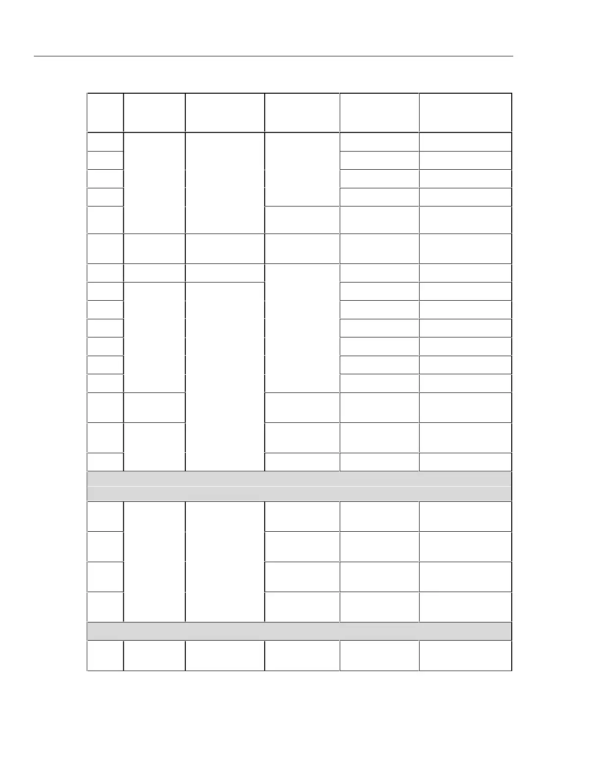
Table 4. 17B Performance Test (cont.)
Step
Test
Function
UUT Switch
Setting
UUT Push
Button
5520A Output UUT Display limits
14 3.5 V dc 3.480 to 3.520 V dc
15 35 V dc 34.80 to 35.20 V dc
16 350 V dc 348.0 to 352.0 V dc
17
N/A
1000 V dc 992 to 1008 V dc
18
Volts DC
V
r
19 STANDBY t icon ON
-992 to -1008 V dc
20 mV dc M 0.35 V dc 345.5 to 354.5 mV dc
21 350 Ω 347.9 to 352.1 Ω
22 3.5 kΩ 3.480 to 3.520 kΩ
23 35 kΩ 34.80 to 35.20 kΩ
24 350 kΩ 348.0 to 352.0 kΩ
25 3.5 MΩ 3.480 to 3.520 MΩ
26
Ohms
N/A
35 MΩ 34.45 to 35.55 MΩ
27 Diode C
(once)
0.7 V dc D icon ON
0.630 to 0.770 V
28 C
(press again)
40 Ω E Icon ON
Beeper On
29
Continuity
F
- 800 Ω Beeper OFF
For step 30, disconnect test leads from the calibrator first, then push r when the reading settles.
This ‘rels out’ test lead and meter capacitances.
30 r STANDBY t icon ON
0.00 to 0.02 nF
31 - 48 nF t icon ON
46.99 to 49.01 nF
32 - 0.48 µF t icon ON
469.9 to 490.1 µF
33
Capacitance
c
-4.8 µF t icon ON
4.555 to 5.045 nF
For step 34, wait 15 seconds for reading to settle.
34 Capacitance c - 48 µF t icon ON
45.55 to 50.45 µF
 Loading...