Digital Multimeter
Performance Tests
13
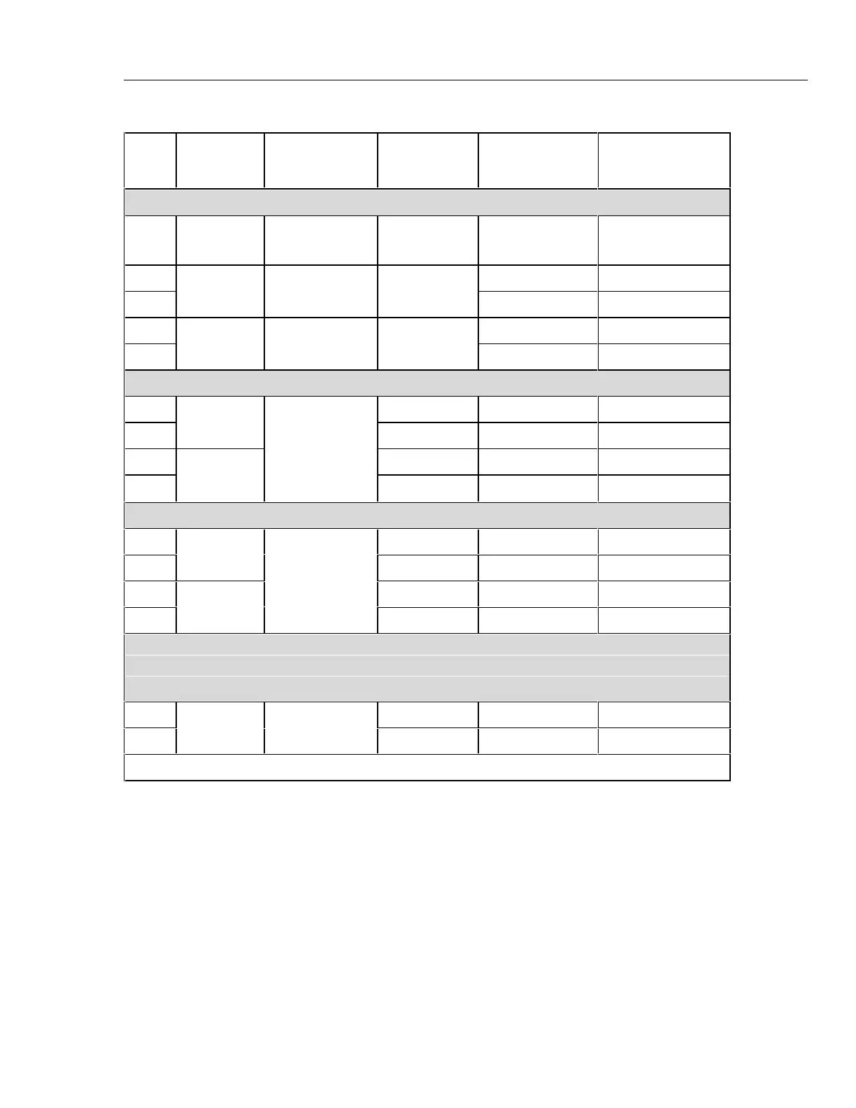
Table 4. 17B Performance Test (cont.)
Step
Test
Function
UUT Switch
Setting
UUT Push
Button
5520A Output UUT Display limits
For step 35, wait 15 seconds for the reading to settle.
35 Capacitance c - 95 µF t icon ON
89.7 to 100.3 µF
36 3.8 A dc 3.713 to 3.887 A dc
37
Amps DC
A N/A
-10 A dc -9.82 to -10.18 A dc
38 10 A 50 Hz 9.82 to 10.18 A ac
39
Amps AC
A C
3.8 A 50 Hz 3.713 to 3.887 A ac
Set 5520A to Standby.
40 38 mA 37.40 to 38.60 mA dc
41
mA dc
- 0.38 A dc 374.0 to 386.0 mA dc
42 C 0.38 A 50 Hz 374.0 to 386.0 mA ac
43
mA ac
m
- 38 mA 200 Hz 37.40 to 38.60 mA ac
Set 5520A to Standby.
44 3.8 mA 3740 to 3860 µA dc
45
µA dc
- 0.38 mA 374.0 to 386.0 µA dc
46 C 0.38 mA 40 Hz 374.0 to 386.0 µA ac
47
µA ac
N
- 3.8 mA 200 Hz 3740 to 3860 µA ac
Set the 5520A to Standby. Connect 5520A temperature output to UUT V Ω terminals using 80AK and K
type Thermocouple wire with male mini connectors at each end. Refer to Figure 2.
Wait 3 to 5 minutes before performing steps 48 and 49 to allow test lead thermals to dissipate.
48 - 380 °C 371.4 to 388.6 °C
49
Temperature
d
- -55.0 °C -48.0 to -62.0 °C
Performance testing of the 17B is now complete.
 Loading...