1750
Calibration Manual
14
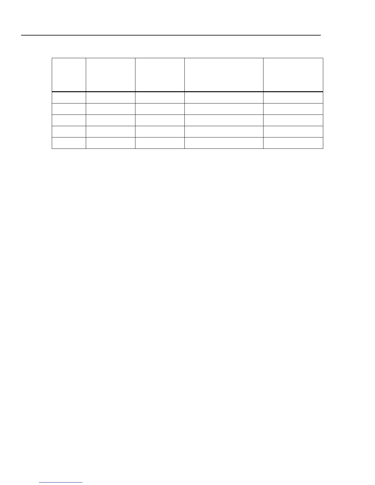
Table 8. Impulse Verification Inputs
Applie
d
Voltage
[Vrms]
Expected
Reading
[Vpk]
Channel
Measured Magnitude
|Vpk|
Limits
[Vpk]
800 1131 AN (A) ± 77
850 1202 BN (B) ± 80
900 1273 CN (C) ± 84
950 1344 NG (N) ± 87
1000 1414 NG (G) ± 91
Calibration
Required Equipment
The required equipment and cables for calibrating the Recorder are listed in Tables 2 and
3.
XWWarning
To avoid electrical shock, personal injury, or fire:
• Do not perform the calibration procedures or calibration
verification tests described in this manual unless you are
qualified to do so.
• Repairs or servicing should be performed only by qualified
personnel.
Calibration Adjustment
The Recorder features closed-case calibration adjustment using known reference sources.
During calibration, the Recorder measures the applied reference source, calculates
correction factors, and stores the correction factors in nonvolatile memory.
Perform calibration adjustment if the Recorder fails any performance test in the
verification procedure.
Note
Calibration should be performed under ambient temperature conditions
between 20
°
C and 30
°
C.
Calibration consists of four parts: I-Wave, I-Rogowski, V-Wave, and V-Impulse. Each
part calibrates one measurement system in the Recorder. For each part, the calibration
values are checked to be sure the Recorder is working correctly and calibration results are
valid. All of the calibration steps for each of the four measurement systems must be
completed before the calibration values can be written to the Recorder’s nonvolatile
memory.
I-Wave, I-Rogowski, and V-Wave channels are calibrated using 55 Hz sine wave signals
to minimize 50 Hz or 60 Hz power line interference with the calibration measurements.
V-Impulse channels are calibrated using dc voltages, averaging calibration measurements
to suppress power line interference.