1750
Calibration Manual
10
Neutral Voltage Verification
1. Connect NORMAL LO to A, B, C, J, and ..
2. Connect the calibrator NORMAL HI to N on the Recorder.
3. Apply the voltages from Table 5, listing the Recorder readings for the appropriate
model.
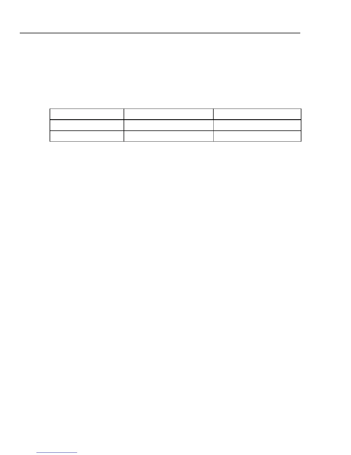
Table 5. Neutral (AC) Voltage Accuracy Check
Applied NG Reading Limits
60 V @ Local Hz ± 1.12 V
100 V @ Local Hz ± 1.20 V
4. Verify that the N LED is on.
5. Set the calibrator to STBY, verify that the LED for N turns off.
6. Disconnect the test leads from the Recorder.
Rogowski Current Verification
1. Verify the resistor in the Rogowski calibration cable is within 0.1 % of 100 kΩ.
2. Connect the calibrator NORMAL HI to Voltage A, B, and C on the Recorder.
3. Connect the calibrator NORMAL LO to N and Voltage J on the Recorder.
4. Connect the calibrator AUX HI and LO to current input A using the Rogowski
calibration cable. See Figure 3.
5. Set the calibrator output to 120.0 V @ 55 Hz on the NORMAL output and the values
from Table 6 the AUX output.
6. Press the WAVE MENUS softkey and ensure the phase angle is -90 °.
7. Press the HARMONIC MENU softkey; ensure the HARMONIC selection is set to
1 and the FUNDMTL selection is set to aux.
8. Press OPR.
9. Set the calibrator to voltages from Table 6 and list the Recorder readings for channel
A.
10. Move cable to next channel and repeat step 9 for channels B, C,
N, and J.