Power Recorder
Verification Tests
11
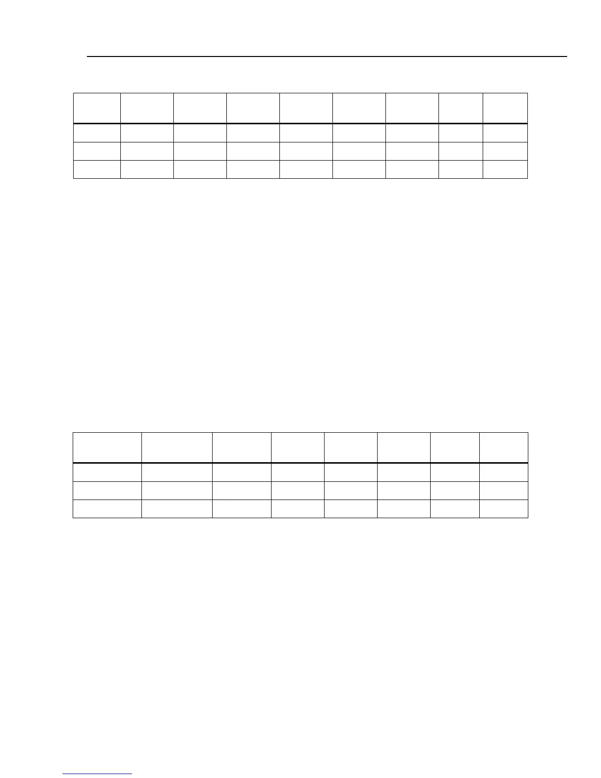
Table 6. Rogowski Current Accuracy Check
Applied
Voltage
Expected
Current
Expected
Reading
A Reading B Reading C Reading N Reading G Reading Limits
0.649 V 6.49 μA 20 A ± 0.20 A
1.6225 V 6.225 μA 50 A ± 0.35 A
3.245 V 32.45 μA 100 A ± 0.60 A
CT Current Verification
1. Connect the calibrator NORMAL HI to Voltage A, B, and C on the Recorder.
2. Connect the calibrator NORMAL LO to Voltage N and J on the Recorder.
3. Connect the calibrator AUX HI and LO to current input A using the current test
cable. See Figure 6. The current test calibration cable connects the voltage to all
current sense inputs and indicates that a 100 A current transformer is attached.
4. Set the calibrator output to 120.0 V @ 50 or 60 Hz on the NORMAL output and the
values from Table 7 on the AUX output.
5. Press the WAVE MENUS softkey and ensure the phase angle is 0.0 °.
6. Press the HARMONIC MENU softkey; ensure the HARMONIC selection is set to
1 and the FUNDMTL selection is set to aux.
7. Press OPR.
8. Set the calibrator to voltages from Table 7 and list the Recorder readings for that
channel.
Table 7. CT Current Accuracy Check
Applied Voltage
Expected
Reading
A Reading B Reading C Reading N Reading G Reading Limits
0.4 V 20 A ± 0.20 A
1.0 V 50 A ± 0.35 A
2.0 V 100 A ± 0.60 A
9. Verify that the current LED is on.
10. Move cable to next channel and repeat steps 8 and 9 for channels B, C, N, and J.
11. Set the calibrator to STBY. Verify that the current LEDs turn off.