Digital Multimeter
Calibration Adjustments
15
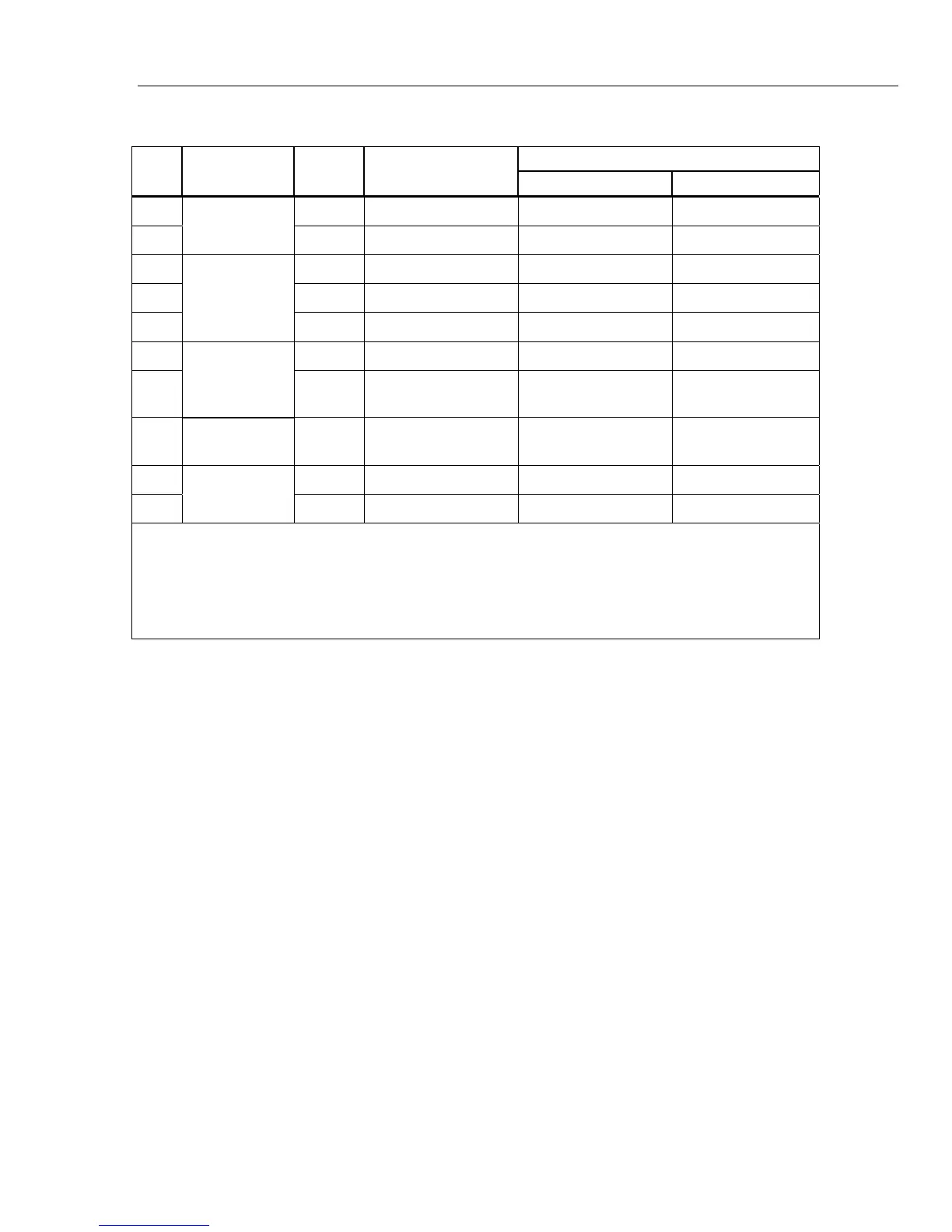
Table 4. Accuracy Tests (cont.)
Step
Test
Function
Range 5520A Output
UUT Measurement
Low Limit High Limit
42
DC Microamps
600 μA 330 μA 328.9 μA 331.1 μA
43 6000 μA 3300 μA 3291 μA 3309 μA
44
Capacitance
10 nF Open input
[1]
0.70 nF 1.10 nF
45 100 nF 5 nF
[2]
4.7 nF 5.3 nF
46 100 μF
9.5 μ
F
9.2 μF 9.8 μF
47
K
Low Pass
Filter
1000 V 400 V, 400 Hz 372 V 408 V
48 1000 V 400 V, 800 Hz
[3]
226 V 340 V
49 VDC Peak
Min/Max
6 V
6 Vpp, 500 Hz Sq.
Wave, DC offset 1 V
-1.798 V to -2.202 V 3.797 V to 4.203 V
50 mVdc
Temperature
[4]
0 °C -1.0 °C 1.0 °C
51
100 °C
98.0 °C 102.0 °C
[1] Remove test leads from unit.
[2] Use REL to compensate for internal Meter and lead capacitance (must disconnect test leads from calibrator before pushing REL)
[3] The Meter accuracy is not specified at this input signal frequency with Low-pass filter selected. The display reading shown, checks
that the Low-pass filter is active and follows an expected roll-off curve.
[4] To ensure accurate measurement, the Meter and thermocouple adapter must be at the same temperature. After connecting the
thermocouple adapter to the Meter allow for reading to stabilize before recording display reading.
Backlight Functional Test
A backlight test is done to make sure the backlight comes on with the first push of H.
The second push causes the backlight to be brighter and a third push turns off the
backlight.
Calibration Adjustments
If one or more of the accuracy tests shows a measurement that is not between the high
and low limits, you can do adjustments. This adjustment procedure sets the Meter to
operate to its specifications.
Note
If the adjustment routine is stopped before you complete the procedure, no
changes are made to the calibration constants in memory.
You must set the Meter to the CAL mode and type in a password to do calibration
adjustments.
Cal Mode Button Functions
For the CAL mode, some of the buttons on the Meter have alternative functions. Some
buttons function differently at different points in the calibration adjustment procedure.
Table 5 is a list of the Meter buttons and their function for the calibration adjustment
procedure.

 Loading...