287/289
Getting Started
6
Understanding the Display
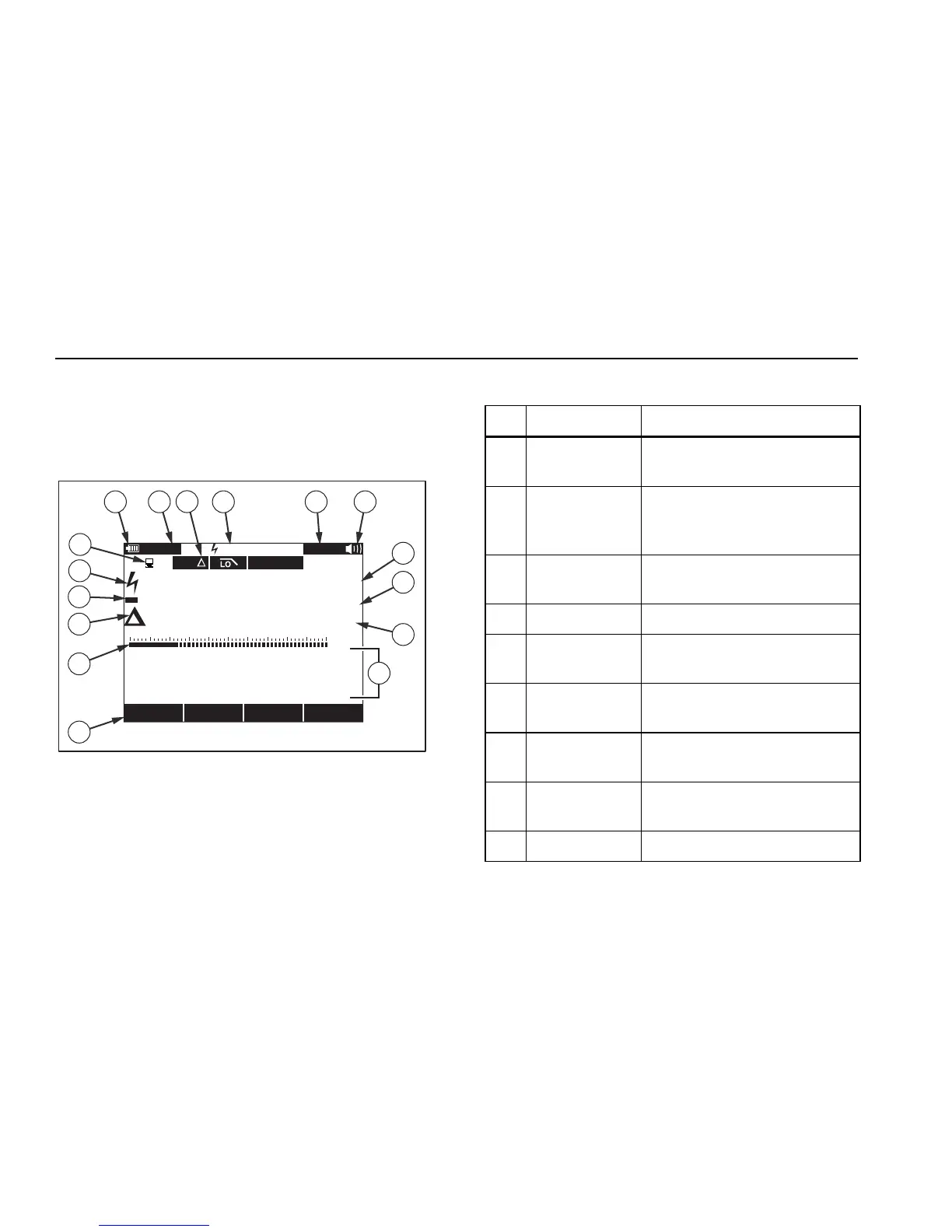
Display features shown in Figure 2 are described in Table 3. Major
display features are described in the 287/289 Users Manual contained on
the accompanying CD.
1
3
4
5
6
10
9
87 11 12
13
14
15
2
AutoHOLD
mVAC
Crest Factor
Hz60.000
Save Setup
Auto Range
5 mVDC
500 VAC0
8:10pm
06/13/07
123.45 VAC
100 200 300 400
AutoSAVEHOLDREL
123.45
16
est01.eps
Figure 2. Display Features
Table 3. Display Features
Item Function Indication
A Softkey labels Indicates the function of the button just
below the displayed label.
B Bar graph Analog display of the input signal (See
the “Bar Graph” section below for more
information).
C Relative Indicates the displayed value is relative
to a reference value.
D Minus sign Indicates a negative reading.
E Lightning bolt Indicates hazardous voltage present at
the Meter’s input.
F Remote
communication
Indicates activity over the
communication link.
G Battery level Indicates the charge level of the six AA
batteries.
H Time Indicates the time set in the internal
clock.
I Mode annunciators Indicates the Meter’s mode.