Calibration and Verification
Full Verification 3
3-35
9. Change the Calibrator frequency to 20 Hz, 40 Hz, 1 kHz, 5 kHz and 10 kHz. At each
frequency record the error display on the 5790A in Table 3-28 or 3-29. Verify that
the results are within limits shown.
10. Repeat steps 2 through 9, but replace the 200Ω metal film resistor with the 2 kΩ
resistor, and use 200 μA instead of 2 mA.
3-22. Rationale for Using Metal-Film Resistors to Measure AC Current
To be able to measure alternating current, a system comprised of a suitable ac shunt and
ac detector is required. First let us consider the ac shunt. For this example we will use a 2
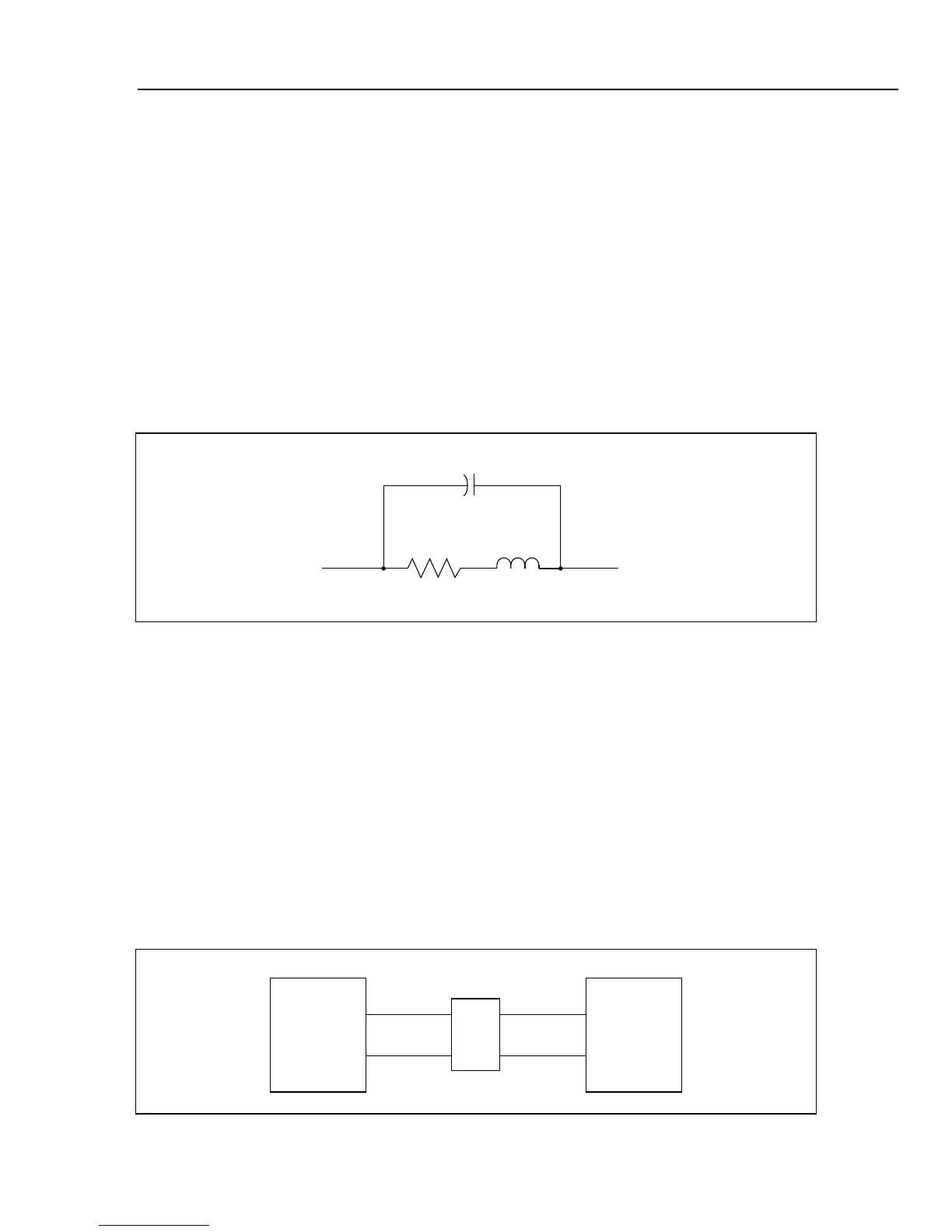
kΩ metal film resistor. At frequencies up to 10 kHz, the equivalent circuit of the resistor
can be illustrated as in Figure 3-12. Values typical for shunt capacitance and series
inductance are 2 pF (Cs) and 0.01 μH (Ls). For comparison, wire has approximately 0.02
μH/inch. At 10 kHz, the reactance of Cshunt is 8 MΩ, and the reactance of Lseries is 0.6
mΩ. The formulae to use are:
SHUNT
C
SERIES
L
R
F3-10.EPS
Figure 3-12. Metal Film Resistor Equivalent Circuit
(1/Z)
2
= (1/R)
2
+ (1/XC)
2
(1)
(Z)
2
= (R)
2
+ (XL)
2
(2)
Where R = resistance Xc = Capacitive Reactance
Z = network impedance XL = Inductive Reactance
We can see that these effects can be ignored, because their contribution to errors in the
measurement process is less than 1 ppm. That is, the metal film resistor's self reactance is
totally dwarfed by the reactance of the measuring circuit, which is overwhelmingly
capacitive.
If a detector as shown in Figure 3-13 has an input impedance of 10 MΩ shunted by 123
pF, then the effects of Xc must be accounted for. We can ignore the net resistance change
introduced by the 10 MΩ detector resistance.
SHUNT
R
DET.UUT
F3-11.EPS
Figure 3-13. Metal Film Resistor in Test Circuit

 Loading...


