5700A/5720A Series II Calibrator
Service Manual
4-6
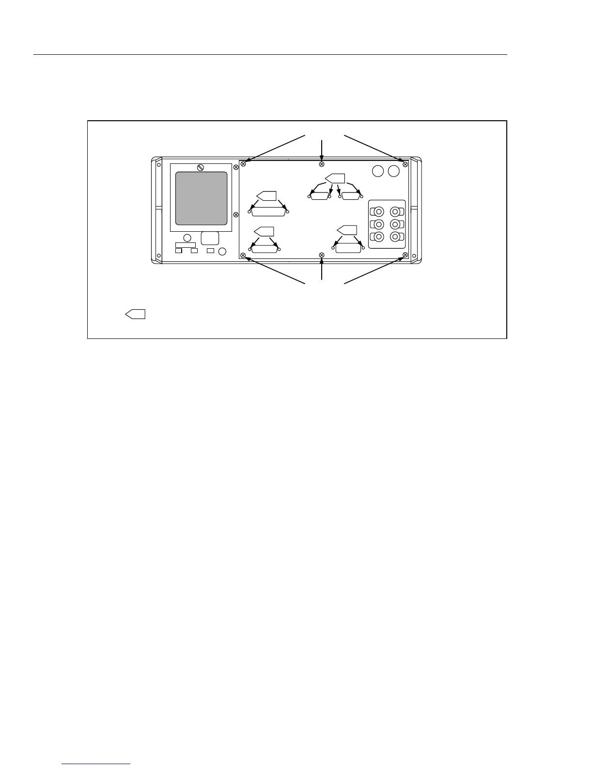
4-11. Rear Panel Assembly Access
Refer to Figure 4-4 during the following procedure:
REMOVE
REMOVE
1 REMOVE FACK SCREWS TO SEPARATE THE REAR PANEL CIRCUIT BOARD FROM
THE METAL HOUSING.
1
1
1
1
F4-3.EPS
Figure 4-4. Rear Panel Assembly Access
1. Remove the six securing screws for the Rear Panel assembly housing.
2. Gently pull the rear panel housing from the Rear Panel.
3. Allow the rear panel housing to lay flat on the work surface by removing the two
ribbon cables from the Rear Panel board.
4. Remove the two nuts at TB1 and TB2 on the paddle board; separate the associated
wires from the paddle board.
5. Remove P11 from J11. Then remove the two paddle board mounting screws and
separate the paddle board from the Rear Panel assembly.
6. Remove the jack screws for each connection on the rear panel housing, then gently
lift the Rear Panel assembly out from the housing.
7. Reverse this procedure to install the Rear Panel assembly.
4-12. Front Panel Removal and Installation
Refer to Figure 4-5 during the following procedure:

 Loading...


