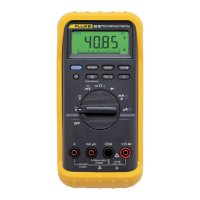
80 Series III
Service Information
8
Electrical Characteristics of the Terminals
L Overload Protection
1
: 1000 V rms
Input Impedance (nominal):
10 MΩ<100 pF
Common Mode Rejection Ratio: >120 dB at dc, 50 Hz or 60 Hz
(1 kΩ unbalance)
Normal Mode Rejection:
>60 dB at 50 Hz or 60 Hz
mA Overload Protection
1
: 1000 V rms
Input Impedance (nominal):
10 MΩ<100 pF
Common Mode Rejection Ratio: >120 dB at dc, 50 Hz or 60 Hz
(1 kΩ unbalance)
Normal Mode Rejection:
>60 dB at 50 Hz or 60 Hz
K Overload Protection
1
: 1000 V rms
Input Impedance (nominal): 10 MΩ<100 pF (ac-coupled)
Common Mode Rejection Ratio: >60 dB, dc to 60 Hz
(1 kΩ unbalance)
e Overload Protection
1
: 1000 V rms
Open Circuit Test Voltage: <1.3 V dc
Full Scale Voltage: To 4.0 MΩ: <450 mV dc
40 MΩ or nS V1.3 V dc
Typical Short Circuit Current: 400 Ω: 200 µA
4 kΩ: 80 µA
40 kΩ: 12 µA
400 kΩ: 1.4 µA
4 MΩ: 0.2 µA
40 MΩ: 0.2 µA
G Overload Protection
1
: 1000 V rms
Open Circuit Test Voltage: <3.9 V dc
Full Scale Voltage: 3.000 Vdc
Typical Short Circuit Current: 0.6 mA typical
1. 10
6
V Hz maximum.
Required Equipment
Required equipment is listed in Table 2. If the recommended models are not available,
equipment with equivalent specifications may be used.
Repairs or servicing should be performed only by qualified personnel.

 Loading...