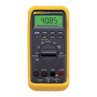
80 Series III
Service Information
16
Table 3. Rotary Switch Test
Rotary Switch Position Display (±12) Rotary Switch Position Display (±12)
OFF
V ac
V dc
mV dc
N/A
0
-32
-64
Continuity/Ohms
Diode test
mA/A
µA
-96
-128
-160
-192
Testing the AC Voltage Function
To verify accuracy in the ac voltage ranges, do the following:
1. Connect the Calibrator to the
z and COM inputs on the Meter.
2. Set the Calibrator for the voltage and frequency called for in step 1 of Table 4.
3. Compare the reading on the Meter display with the display reading for your 80
Series III model (83, 85, or 87) shown in Table 4.
If the display reading falls outside of the range shown in Table 4, the Meter does not
meet specification.
4. Repeat this procedure for steps 2 through 17 of Table 4.
Table 4. AC Voltage Test
Input Display Reading
Step Voltage Frequency 83 Series III 85/87 Series III
1 350.0 mV 60 Hz 347.8 to 352.2 347.1 to 352.9
2 350.0 mV 1 kHz 346.1 to 353.9 346.1 to 353.9
3 350.0 mV 5 kHz 342.6 to 357.4 342.6 to 357.4
4 350.0 mV 20 kHz NA 341.0 to 359.0
5 3.500 V 60 Hz 3.480 to 3.520 3.473 to 3.527
6 3.500 V 1 kHz 3.461 to 3.539 3.461 to 3.539
7 3.500 V 5 kHz 3.426 to 3.574 3.426 to 3.574
8 3.500 V 20 kHz NA 3.410 to 3.590
9 35.00 V 60 Hz 34.80 to 35.20 34.73 to 35.27
10 35.00 V 1 kHz 34.61 to 35.39 34.61 to 35.39
11 35.00 V 5 kHz 34.26 to 35.74 34.26 to 35.74
12 35.00 V 20 kHz NA 34.10 to 35.90
13 350.0 V 60 Hz 348.0 to 352.0 347.3 to 352.7
14 350.0 V 1 kHz 346.1 to 353.9 346.1 to 353.9
15 350.0 V 2.5 kHz 342.6 to 357.4 342.6 to 357.4
16 900V 60 Hz 893 to 907 892 to 908
17 900 V 1 kHz 887 to 913 887 to 913

 Loading...