80 Series III
Service Information
18
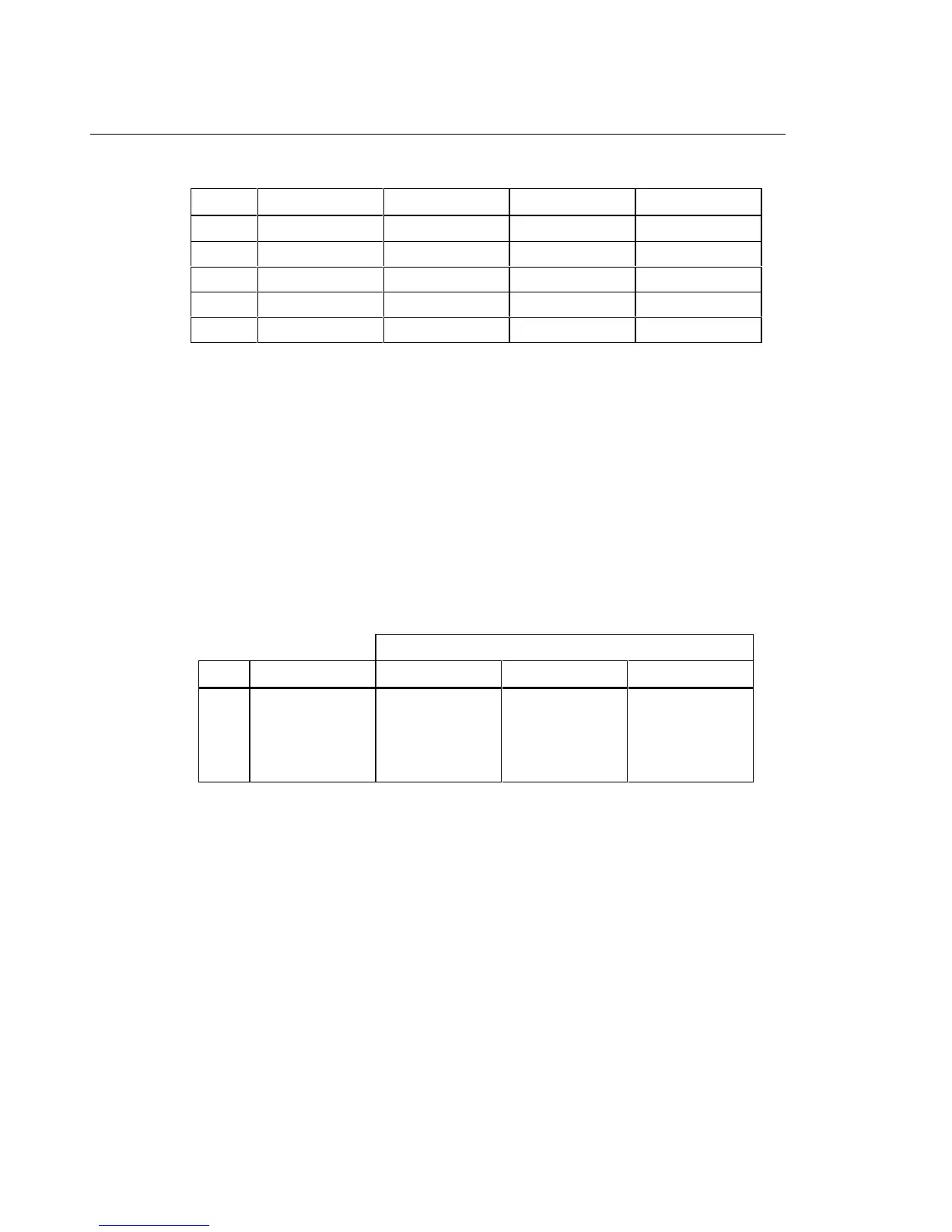
Table 6. Frequency Counter Sensitivity and Trigger Level Tests
Step Range Amplitude (RMS) Frequency Display Reading
1 4 V ac 300 mV ac 1 kHz 999.8 - 1000.2
2 4 V dc 1.7 V ac 1 kHz 999.8 - 1000.2
3 4 V dc 1.0 V ac 1 kHz 000.0
4 40 V dc 6.0 V ac 1 kHz 999.8 - 1000.2
5 40 V dc 2.0 V ac 1 kHz 000.0
Testing DC Voltage
To verify accuracy of the dc voltage function, do the following. (A separate performance
test procedure for mV dc is provided later in this section).
1. Connect the Calibrator to the
z and COM inputs on the Meter.
2. Turn the rotary switch to L.
3. Apply the input from step 1 of Table 7 for your model 80 Series III.
4. Compare the reading on the Meter display with the display reading in Table 7.
If the display reading falls outside of the range shown in Table 7, the Meter does not
meet specification.
5. Repeat steps 3 and 4 for the remaining inputs shown in Table 7.
Table 7. DC Voltage Test
Display Reading
Step DC Input Voltage 83 III 85 III 87 III
1
2
3
4
5
3.500 V
35.00 V
-35.00 V
350.0 V
1000 V
3.495 to 3.505
34.95 to 35.05
-34.95 to -35.05
349.5 to 350.5
998 to 1002
3.496 to 3.504
34.96 to 35.04
-34.96 to -35.04
349.6 to 350.4
998 to 1002
3.497 to 3.503
34.97 to 35.03
-34.97 to -35.03
349.7 to 350.3
998 to 1002
Testing the PEAK MIN MAX Function (Model 87 only)
To check minimum/maximum (MIN MAX) feature of the Model 87.
1. Connect the Calibrator to the
z and COM inputs on the Meter.
2. Apply 2.0 V ac at 60 Hz (step 1, Table 8) from the Calibrator to the
z and
COM inputs of the Meter.
3. Turn the rotary switch to L (dc volts for dc-coupling of the input) or K (ac volts for
capacitive-coupling of the input).
Note
The rms converter is not used in Peak mode. The digital display
represents the actual peak value of the input.
4. Press M.
5. Press the T(beeper) to enter the
PEAK MIN MAX mode and begin displaying
maximum values.

 Loading...


