rita0620.eps
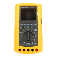
Figure 2-10. LOGIC Testing
Testing for Logic Activity
(not available on Model 863)
6
Turn the Selector to LOGIC.
7
Connect the test leads
as shown.
8
Use the LOGIC Testing Softkeys as shown.
9
The following hardkeys can be used
:
d P M
For the logic activity indicator,
[
represents a logic
high, and
]
represents a logic low. A horizontal bar
represents an indeterminate condition (no high or
low detected since the previous reading.) The logic
indicator flashes at a 10 Hz rate for activity faster
than 10 Hz or at the actual rate if activity is slower
than 10 Hz.
The actual logic frequency is shown in the primary
display. Frequencies to 10 MHz and higher can be
measured. DC Volts levels are shown in the
secondary display.

 Loading...