True-rms Multimeter
Calibration Adjustment
19
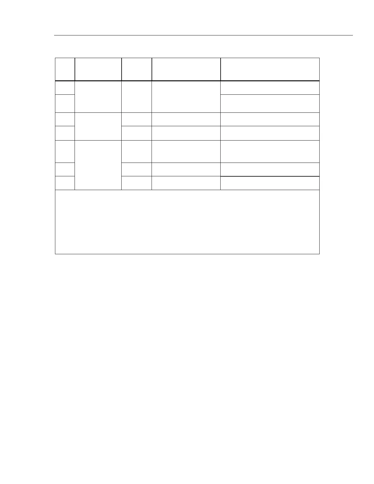
Table 5. Accuracy Tests (cont.)
Step
Test
Function
Range 5500A Output Display Reading
47
Max = 5.896 to 6.104
48
L
(87 and 88 only)
Peak Min/Max
6 V dc 8 Vpp, 2 kHz Sq.
Wave, DC offset 2 V
Min = -1.898 to -2.102
49
0 °C -1.0 to 1.0
50
m
L
(87 and 88 only)
Temperature
3
100 °C 98.0 to 102.0
51
Press backlight button Backlight comes on
52
Press backlight button Backlight Intensifies
53
Backlight
Press backlight button Backlight off
1. Or short test leads and use REL to offset test lead resistance.
2. Remove test leads from unit.
3. To ensure accurate measurement, the Meter and thermocouple adapter must be at the same temperature. After
connecting the thermocouple adapter to the Meter allow for reading to stabalize before recording display reading.
4. The Meter accuracy is not specified at this input signal frequency with Low-pass filter selected. The display reading
shown, check that the Low-pass filter is active and follows an expected roll-off curve.
5. Use REL to compensate for internal Meter and lead capacitance. Test leads must be disconnected from the
calibrator before using REL.
6. W 10 A continuous up to 35 °C; < 20 minutes on, 5 minutes off at 35 °C to 55 °C. 20 A for 30 seconds maximum;
>10A unspecified.
Calibration Adjustment
The Meter features closed-case calibration adjustment using known reference sources.
The Meter measures the applied reference source, calculates correction factors and stores
the correction factors in nonvolatile memory.
The following sections present the features and Meter pushbutton functions that can be
used during the Calibration Adjustment Procedure. Perform the Calibration Adjustment
Procedure should the Meter fail any performance test listed in Table 6.
Calibration Adjustment Counter
The Meter contains a calibration adjustment counter. The counter is incremented each
time a Calibration Adjustment Procedure is completed. The value in the counter can be
recorded and used to show that no adjustments have been made during a calibration
cycle.
Use the following steps to view the Meter's calibration counter.
1. While holding down B, turn the rotary knob from OFF to VAC. The Meter
should display “Z CAL”.
2. Press D once to see the calibration counter. For example "n001".
3. Turn the rotary knob to OFF.
 Loading...