4
• Do not look into the laser. Do not point laser directly at persons or
animals or indirectly off reective surfaces.
• When you inspect ber endfaces, use only magnication devices
that have the correct lters.
• Use the Product only as specied or hazardous laser radiation
exposure can occur.
WCaution
To prevent damage to the Product or cables under test and to prevent
data loss, read all safety information given in all documentation supplied
with the Product.
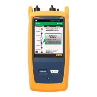
Connectors, Keys, and LEDs
A
LCD display with touchscreen.
B
Singlemode OTDR port with an APC endface, interchangeable SC adapter,
and protective cap. The LED in front of the port turns on when the port
emits an optical signal.
C
Visual fault locator port and protective cap. The LED in front of the port
turns on when the port emits an optical signal.
D
Button that controls the VFL.
E
Micro USB port: This USB port lets you connect the tester to a PC so you
can upload test results to the PC and install software updates in the tester.
F
Type A USB port: This USB host port lets you save test results on a USB flash
drive and connect the FI-1000 video probe to the tester. Versiv: Also lets
you connect a Wi-Fi adapter for access to Fluke Networks cloud services.
(Versiv 2 testers have an internal Wi-Fi radio.)
G
Headset jack.
H
: Starts a test. To start a test, you can also tap TEST on the display.
I
Power button. Versiv 2: The LED in the power button shows the status of
the battery charging process. See the Users Manual.