Fluke 19xB-19xC-2x5C
Service Manual
5. To get access to the input circuits on the PCA, unscrew the Torx screws item 7 and
remove the metal input circuit shielding boxes.
ST8676.WMF
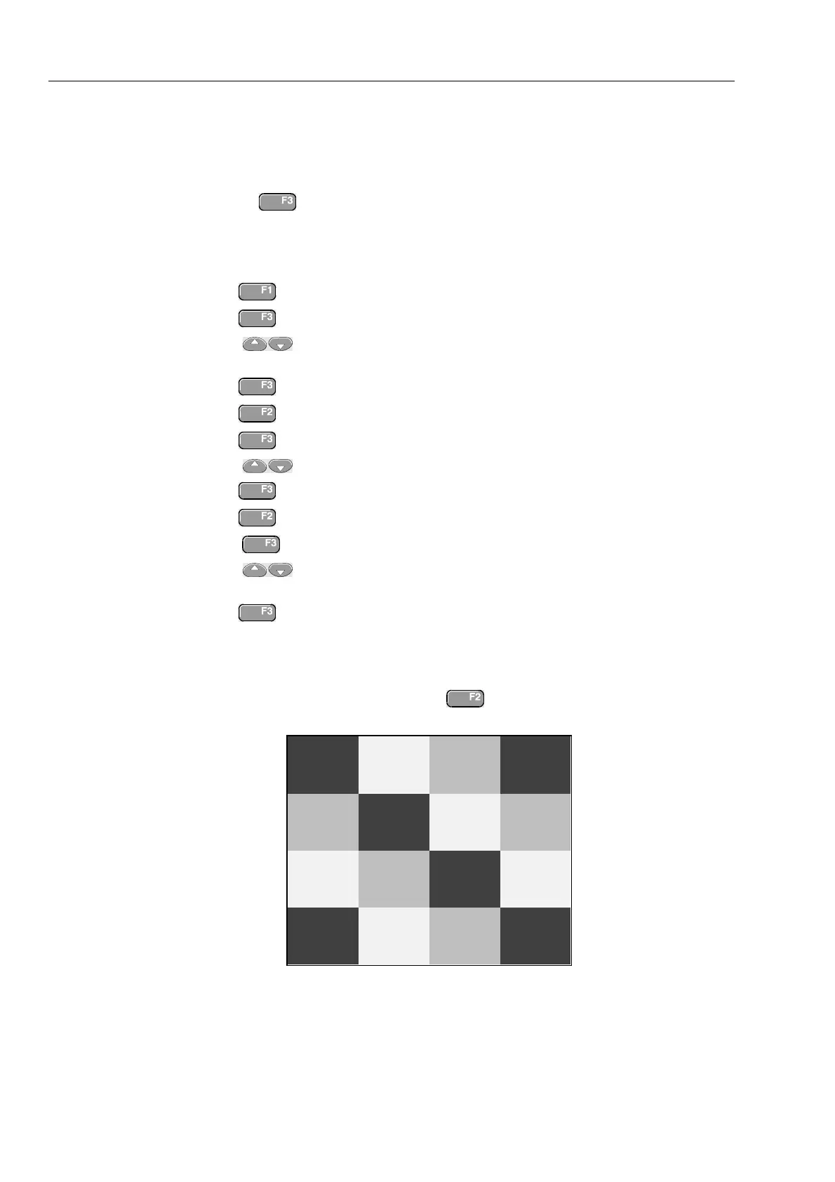
Figure 6-7. PCA Unit Assembly
6.2.10 Reassembling the Main PCA Unit
Reassembling the main PCA unit is the reverse of disassembly (see figure 6.7). However
you must follow special precautions when reassembling the main PCA unit.
1. Install the metal input circuit shielding boxes (items 6) carefully. Take care that the
notches at the edges of the boxes match the holes in the PCA. The plate spring in the
Input A and Input B box must touch the C-ASIC N1000 (Input A) or N1200 (Input
B) for cooling. Do not bend the springs!
Caution
A good thermal coupling between the C-ASIC’s (N1000, N1200)
and the input boxes is achieved by self adhesive thermal
conductive pads. These pads can either be stuck on the spring
in the box, or on the C-ASIC. If stuck on the C-ASIC, you can re-
use the pad when replacing the C-ASIC.
2. Attach the isolation strip carefully! Insert the ends of the strip into the slots in the
PCA, and push firmly until the strip is in its original position.
3. Put the PCA in the shielding box, and fasten the 2 hexagonal standoffs (item 10).
4. Attach the shielding cover (item 8). Ensure that the small optical gate PCA mounted
on the main PCA sticks through the slot in the shielding cover.
5. Ensure that the rubber sealing ring (item 5) for the power connector is present