T+ and T+ PRO
Calibration Information
8
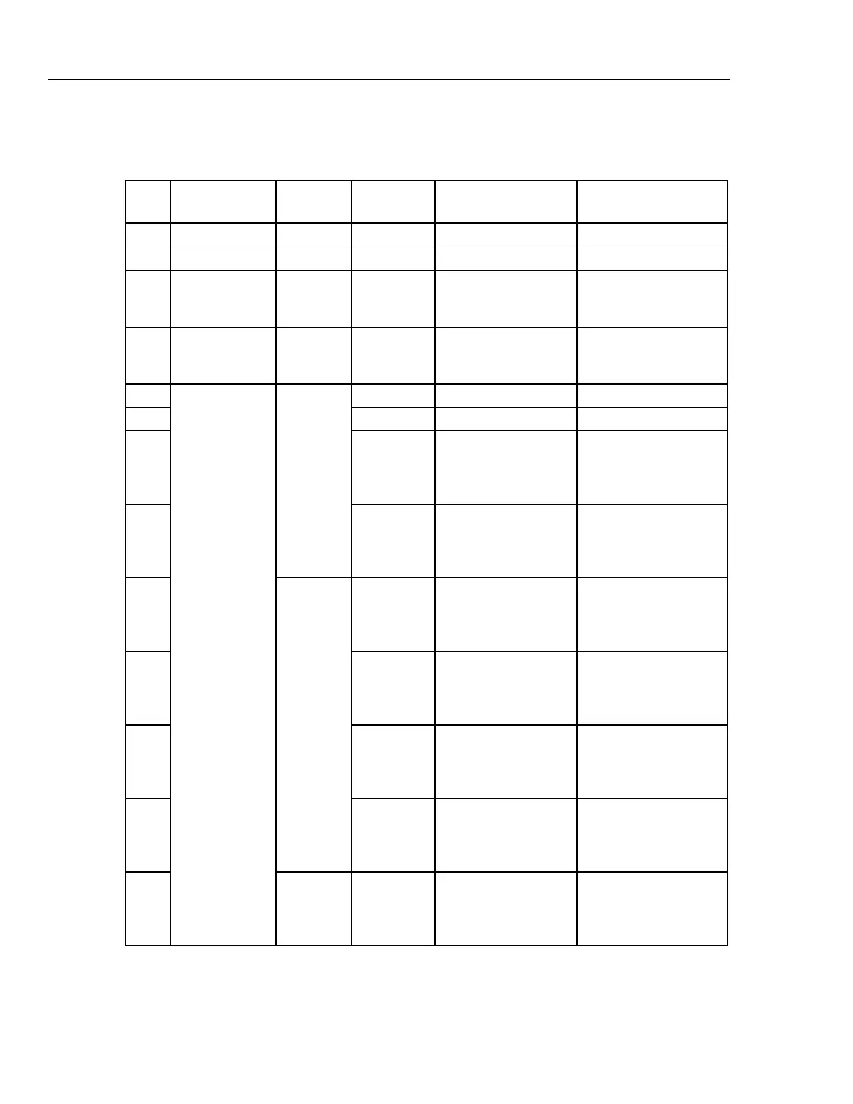
Accuracy Tests
Perform the accuracy and verification tests in Table 3.
Table 3. T+ and T+ PRO Accuracy Tests
Step Function Range
Input
Value
UUT Response
(LED)
LCD Display (T+ PRO)
Measurement Limits
1 Pos Off 12 V +20 V 12 V LED On - - -
2 Neg Off 12 V −20 V 12 V LED On - - -
3 Pos On 24 V +40 V
+ LED On
12 V, 24 V LED On
Hazard On
- - -
4 Neg On 24 V −40 V
− LED On
12 V, 24 V LED On
Hazard On
- - -
5
Digital Display
Voltage
Measurement
dc V
0 – 50 V
+10.5 V 12 V LED On 10.1 to 10.9
6 −10.5 V 12 V LED On −10.1 to −10.9
7 +48 V
+ LED On
12 – 48 V LED On
Hazard On
Beeper & Vibration On
46.8 to 49.2
8 −48 V
− LED On
12 – 48 V LED On
Hazard On
Beeper & Vibration On
−46.8 to −49.2
9
dc V
0 – 600 V
+55 V
+ LED On
12 – 48 V LED On
Hazard On
Beeper & Vibration On
52 to 58
10 −55 V
− LED On
12 – 48 V LED On
Hazard On
Beeper & Vibration On
−52 to −58
11 +590 V
+ LED On
12 – 600 V LED On
Hazard On
Beeper & Vibration On
576 to 604
12 −590 V
− LED On
12 – 600 V LED On
Hazard On
Beeper & Vibration On
−576 to −604
13
ac V
0 – 600 V
55 V, 60 Hz
ac LED On
12 – 48 V LED On
Hazard On
Beeper & Vibration On
51 to 59