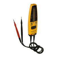
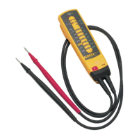
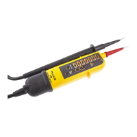
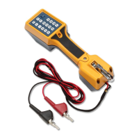
Electrical Tester
Performance Tests
9
Table 3. T+ and T+ PRO Accuracy Tests (cont.)
Step Function Range
Input
Value
UUT Response
(LED)
LCD Display (T+ PRO)
Measurement Limits
14
Voltage LEDs
24 V 24 V 24 V LED On - - -
15 120 V 120 V 120 V LED On - - -
16 208 V 208 V 208 V LED On - - -
17 240 V 240 V 240 V LED On - - -
18 277 V 277 V 277 V LED On - - -
19
347 V
(Canada)
347 V 347 V LED On - - -
20 480 V 480 V 480 V LED On - - -
21 Continuity 0 – 20 kΩ Short Continuity LED On Continuity Sign
22
Resistance 0.00 – 9.99 kΩ
Short None 0.00 to 0.03
23 100 Ω None 0.06 to 0.14
24 9 kΩ None 8.52 to 9.48
Load Current Test
To test the load current, set up the UUT with equipment as shown in Figure 2 and complete the
following procedure:
1. Set the DMM to the mA dc function.
2. Apply 600 V dc from the Source. The DMM reading should be < 5 mA.
3. Apply −600 V dc from the Source. The DMM reading should be < 5 mA.