5
Physical Characteristics
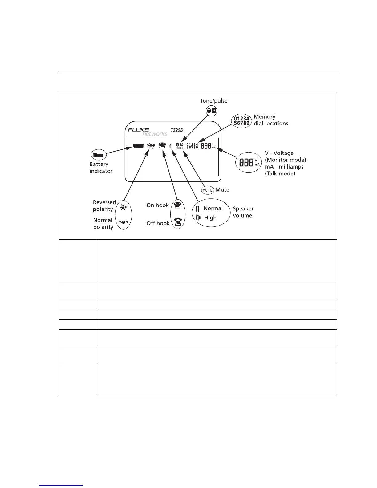
Figure 2. TS25D Test Set Icons
cac02.eps
Polarity In Monitor or Talk mode, the polarity icon indicates the dc polarity of the line. The Tip-Ring icon
with no X indicates the red test lead is connected to the Ring (negative) side of the line and the
black test lead is connected to the Tip (positive) side of the line. When the Tip-Ring polarity icon
has an X through it, the test leads are reversed; that is, the red test lead is connected to the Tip
(positive) side and the black test lead is connected to the Ring (negative) side. No icon appears
when the leads are disconnected or the line is not powered.
Battery The battery icon indicates the battery’s charge level. The battery level is continuously displayed in
Monitor and Talk mode.
On/off hook The telephone icon tells you if the test set is on or off hook.
Mute The MUTE icon appears when the microphone is muted.
Tone/Pulse In tone mode the icon is a T; in pulse mode it is a P.
Speaker
volume
The speaker icon appears when the speaker is on.
Memory dial
locations
The test set lets you store 10 numbers in ten memory locations (0 through 9). The icon shows the
number of the active memory location.
V
mA
The test set displays the voltage across Tip and Ring when the test set is on-hook. The test set
displays the current it draws from the line when off-hook.
Voltmeter range: 0 Vdc to 250 Vdc
Current meter range: 0 mA to 110 mA