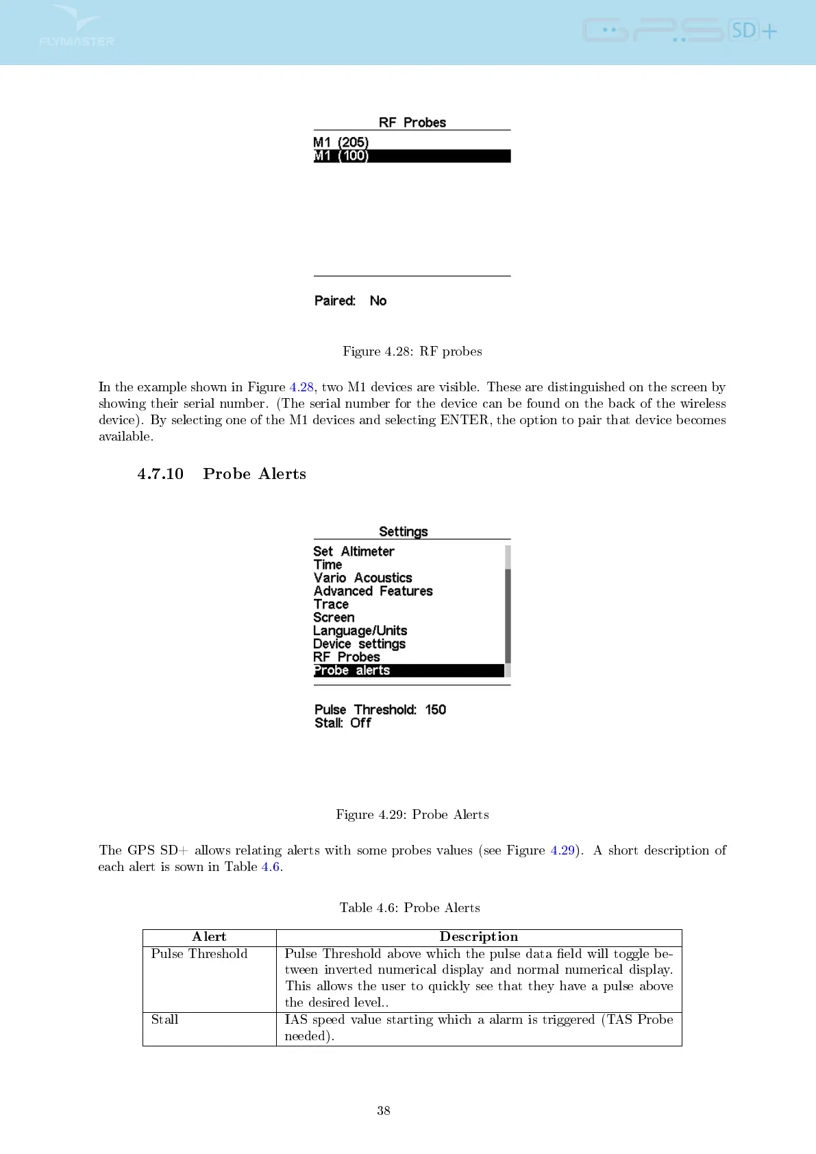
Figure 4.28: RF probes
In the example shown in Figure 4.28, two M1 devices are visible. These are distinguished on the screen by
showing their serial number. (The serial number for the device can be found on the back of the wireless
device). By selecting one of the M1 devices and selecting ENTER, the option to pair that device becomes
available.
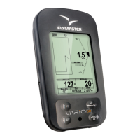
4.7.10 Probe Alerts
Figure 4.29: Probe Alerts
The GPS SD+ allows relating alerts with some probes values (see Figure 4.29). A short description of
each alert is sown in Table 4.6.
Table 4.6: Probe Alerts
Alert Description
Pulse Threshold Pulse Threshold above which the pulse data eld will toggle be-
tween inverted numerical display and normal numerical display.
This allows the user to quickly see that they have a pulse above
the desired level..
Stall IAS speed value starting which a alarm is triggered (TAS Probe
needed).
38