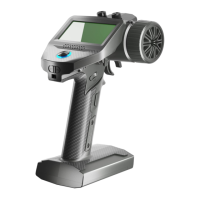
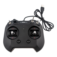
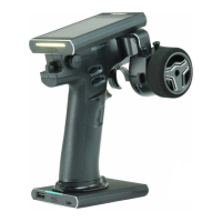
The FMS-G3 is a digital proportional radio control system designed for remote control of 1:18 and 1:24 simulation cars or rock crawlers. It operates on the 2.4GHz ISM band using the AFHDS 2A-BS protocol, providing a resolution of 1024. The transmitter is powered by four 1.5V AA alkaline batteries and has a working current of 120mA/6V. It boasts a maximum power output of less than 20dBm (e.i.r.p.) in EU regions and offers a control distance of over 100 meters. The physical dimensions of the transmitter are 115.275.5145mm, and it weighs 113g. The device is certified with CE and FCC ID: 2A2UNG300.
Function Description:
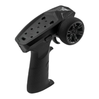
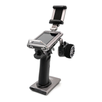
The FMS-G3 transmitter features a CH1 Steering Wheel and a CH2 Throttle Trigger for primary control. It includes a CH3 Three-position Switch for additional functions. For user convenience, it has a Neck Strap Hook. The handle is designed to accommodate four removable batteries. The transmitter is equipped with a Logo Sticker and an LED indicator for status updates. Control buttons include a BIND Button for pairing with receivers, ST- Button (Steering trim or D/R decrease), TH- Button (Throttle trim or D/R decrease), and a Power Switch. Further controls include a REV Button (Steering/Throttle reverse), ST+ Button (Steering trim or D/R increase), and TH+ Button (Throttle trim or D/R increase).
Important Technical Specifications:
- Product Name: FMS-G3
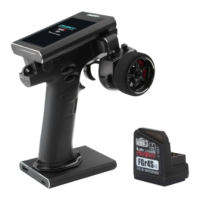
- Compatible Receiver: FMS-R3A
- Model Type: 1:18, 1:24 simulation cars or rock cars
- PWM Channels: 3
- RF: 2.4GHz ISM
- 2.4G Protocol: AFHDS 2A-BS
- Resolution: 1024
- Maximum Power: < 20dBm (e.i.r.p.) (EU)
- Antenna: Singal internal antenna
- Input Power: Powered by 4*1.5V AA alkaline batteries
- Working Current: 120mA/6V
- Distance: >100m
- Online Update: No
- Dimensions: 115.275.5145mm
- Weight: 113g
- Certifications: CE, FCC ID: 2A2UNG300
Usage Features:
- Power On: To power on the transmitter, ensure batteries are fully charged and installed correctly, then switch the Power Switch to the ON position. The transmitter LED will illuminate green.
- Binding: To bind with the receiver, press and hold the BIND button while powering on the transmitter. The transmitter LED will flash fast. Power on the receiver, and its LED will flash quickly. Once binding is complete, the transmitter LED stops flashing and remains solid on. If the transmitter disconnects from the receiver, the transmitter LED will enter a three-flash-one-off state.
- Trims: The ST+ and ST- buttons are used for increasing/decreasing the trim value of CH1, while TH+ and TH- buttons adjust the trim value of CH2. A short beep indicates a successful trim adjustment, and a long beep signifies the end of the trim range.
- Channel Reverse: The REV button reverses the direction of CH1 (steering) and CH2 (throttle). A single beep confirms the reversal, and different beeps for CH1 and CH2 indicate the change.
- D/R Adjustment: CH1 D/R can be adjusted by ST+/- buttons, with a range of 0-120% and a default value of 100%. CH2 D/R can be adjusted by TH+/- buttons, also with a range of 0-120% and a default value of 100%. A short beep confirms adjustment, and a long beep indicates the end of the range.
- Failsafe: To set failsafe, turn on the transmitter, set the desired channel output values, then press and hold the BIND button for 3 seconds. A long beep on tone 1 confirms successful failsafe setting. The default failsafe setting is the last output value. Rebinding the transmitter resets failsafe to its default setting.
- Stick Calibration: To calibrate, turn the Steering Wheel to its maximum clockwise endpoint and push the trigger forward to its maximum endpoint while powering on the transmitter to enter calibration mode. Then, move the Steering Wheel or trigger to their Max or Min endpoints and return to neutral. Press the BIND button to exit calibration mode.
- Data Resetting: To reset data, press and hold the BIND button and the REV button simultaneously while powering on the transmitter. A long beep confirms successful data reset.
- Idle Alarm and Sleep Mode: If the transmitter is not operated for over 10 minutes, it enters idle alarm state. Any control operation will exit this mode. After 2 minutes in idle alarm state, the transmitter enters sleep mode, indicated by a gradual light state of the LED. Repowering the transmitter exits sleep mode. In sleep mode, the buzzer and RF are off, and the transmitter does not respond to controls.
- Low Voltage Alarm: When the transmitter voltage drops below 4.2V, it enters low voltage alarm mode, and the LED flashes slowly. If the voltage drops below 3.5V, the RF is turned off.
- Reminder: If the bound receiver is turned off or disconnects for more than 2 seconds, the transmitter will enter reminder mode, indicated by a three-flash-one-off LED pattern. The transmitter will exit reminder mode once it receives information from the receiver.
Maintenance Features:
- Battery Replacement: Risk of explosion if the battery is replaced by an incorrect type. Dispose of used batteries according to instructions.
- Environmental Protection: Old electrical appliances must be disposed of separately, not with residual waste. They should be taken to communal collecting points for free disposal, contributing to the recycling of valuable raw materials and proper treatment of toxic substances.
- General Precautions: Avoid using the product at night or in bad weather (rain, thunderstorms) to prevent erratic operation or loss of control. Do not use when visibility is limited or expose to moisture. Interference can cause loss of control; avoid operating near other radio control activities, people/roads, passenger boats on ponds/lakes, or power lines/communication antennas. Do not operate when tired, uncomfortable, or under the influence of alcohol/drugs. Maintain line of sight with the model and avoid gripping the transmitter antenna during operation. Do not touch hot parts of the model (engine, motor, speed control) immediately after use to prevent burns. Ensure proper installation of the product in the model. Disconnect the receiver's battery before turning off the transmitter. Verify correct motor direction. Keep the model within range to prevent loss of control.