
А
АртемFeb 28, 2026
Как снять внешний аккумулятор с передатчика
Как снять внешний аккумулятор с передатчика
Highlights warnings and their meanings for safe operation and to prevent damage or injury.
Provides essential safety guidelines for operating the product, covering prohibited and mandatory actions.
Details the advantages and capabilities of the AFHDS 3 digital wireless system, including bidirectional data transmission.
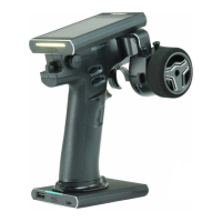
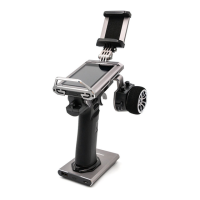
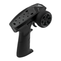
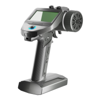
Illustrates and labels the main components and controls of the Noble NB4+ transmitter.
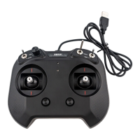
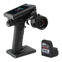
Provides an overview of the FGr4B receiver, including its components and LED status indicator.
Step-by-step instructions for installing and attaching the battery for the transmitter, including safety warnings.
Instructions for safely powering on the transmitter and connecting the receiver, with important operational notes.
Steps for re-binding the transmitter and receiver, including notes on classic and enhanced editions.
Explains the function and color settings of the transmitter's LED indicator.
Instructions for safely powering off the transmitter and receiver system, emphasizing disconnection order.
Explains the Reverse function to correct servo or motor direction and provides setup steps.
Details Endpoints Adjustment for controlling channel range limits, including setup and parameter adjustment.
Describes SUBTRIM for adjusting channel neutral position to correct structural errors or alignment issues.
Explains the Steering Dual Rate/Exponential function for adjusting steering response curve, with setup details.
Details the Throttle Dual Rate/Exponential function for adjusting throttle response curve, similar to ST DR/EXP.
Explains the Auto Braking System function to prevent wheel lock-up and improve control, detailing its submenus.
Covers TIMER functions for calculating model run time, competition time, or transmitter run time, with activation modes.
Explains the key assignment function to link switches and controls to various functions for quick access and control.
Allows customization of function names and selection of preset Chinese names for channels.
Provides functions to manage models, including selecting, naming, resetting, copying, and exporting models.
Details how to display sensor information received by the receiver, including sensor type, ID, and real-time value.
Allows adjustment of steering speed, forward speed, brake speed, and response speeds for channels.
Explains setting up mixing functions like 4WS Mixing, Brake Mixing, and Programming Mixes for advanced control.
Describes TH MID function for setting throttle neutral position to correct uneven throttle/brake travel.
Sets a 'dead zone' for throttle control, ensuring neutral output until trigger movement.
Adjusts throttle response speed at different positions, allowing non-linear output curves.
Enables idle up for engines that might stall, ensuring a minimum throttle to prevent stalling.
Sets the throttle channel to a predefined position when Engine Cut is triggered via a button.
Enables cruise control for maintaining a set speed, with options for manual acceleration.
Activates boat mode, setting throttle to lowest position and disabling brake functionality.
Displays model channel output and allows servo testing for output and range.
Offers a beginner mode to enhance safety by limiting throttle servo amount, suitable for entry-level users.
Provides Smart Vehicle Control for gyroscope calibration and adjustment of steering/throttle gain for specific receivers.
Used to put the transmitter into binding state to connect with the receiver. See section 4.2 Bind.
Adjusts steering force amount for receiver servos when RF setting is Mini-Z(FHSS).
Adjusts receiver gyroscope sensitivity when RF setting is Mini-Z(FHSS).
Sets receiver output mode, including classic and enhanced version interface protocols like PWM, PPM, S.BUS, i-BUS.
Configures failsafe behavior for i-BUS-out and PPM signals, including no output, free, fixed value, or hold.
Selects channel data PWM signal frequency, including analog, digital, SR, SFR, and custom options.
Used to set up i-BUS2 devices, referring to section 6.25 i-BUS2.
Sets up the i-BUS expansion module for servo expansion and connecting devices.
Configures receivers as PWM converters to output PWM signals, applicable to classic and enhanced versions.
Selects a channel to output receiver signal strength value, useful for FPV players.
Detects receiver or sensor battery voltage status, providing high/low voltage alarms.
Tests wireless communication between transmitter and receiver at a close distance to ensure normal operation.
Calibrates BVD voltage when detected voltage deviates from actual values, for classic version receivers.
Enables or disables the Low Signal Alarm function, which triggers when receiver signal strength is low.
Guides on updating receiver firmware after transmitter firmware updates, with detailed steps.
Supports Type-C port output signals for simulator and trainer/head tracker functions.
Sets the overall system color style with options like Technology Cyan, Vibrant Yellow, Bright Red, and Fresh Blue.
Sets wallpapers for the home screen and main menu, with preview functionality.
Allows selection of units for length (metric/imperial) and temperature (Celsius/Fahrenheit).
Controls backlight brightness and timeout, affecting power consumption and battery life.
Enables/disables various sounds like system, alarm, power-on/off, trim, timer, sensor, and menu operation sounds.
Enables/disables vibration for different functions and adjusts vibration levels.
Changes LED strip color, adjusts brightness, and can be set as power capacity indication.
Customizes sliding screen functions for quick access to interfaces like timer or system settings.
Sets screen lock states to prevent accidental parameter changes or operations.
Sets standby timeout intervals or disables standby timeout alarms, with options for time and notification.
Automatically shuts down the transmitter if no operation is detected for a set period to save battery.
Corrects mechanical deviations in throttle trigger and steering wheel for accurate self-centering and travel.
Guides on updating transmitter firmware via USB Type-C cable, warning about data reset.
Resets all transmitter settings and functions to their factory default state.
Displays basic product information, including firmware version, date, hardware, and RF library.
Lists detailed technical specifications for the Noble NB4+ transmitter, including RF, power, display, and dimensions.
Details technical specifications for the FGr4B receiver, including PWM channels, RF protocol, input power, and certifications.
Declares compliance of the Radio Equipment [Noble NB4+, NB4+] with RED 2014/53/EU.
Provides warnings regarding antenna installation and operating conditions for RF exposure compliance.
Instructs on proper disposal of old electrical appliances and batteries to promote recycling and prevent hazards.
States FCC compliance for Class B digital devices and conditions for operation to prevent harmful interference.
| Channels | 4 |
|---|---|
| Frequency Range | 2.4GHz |
| Telemetry | Yes |
| Weight | 520g |
| RF Protocol | AFHDS 3 |
| Data Output | Micro USB |
| Online Update | Yes |
| Low Voltage Warning | Yes |
| Battery Type | LiPo |
| Display | 3.5-inch full-color TFT touch screen |
| Model Type | Car, Boat |
| Temperature Range | -10°C to 60°C |
| Charging Interface | USB Type-C |
| Dimensions | 190mm x 105mm x 165mm |
| Model Memory | 20 |
| RF Power | <20dBm |
| Operating Voltage | 3.5~9V DC |