E 167 - GB - 6
14
Rue du Pré Neuf - 58440 MYENNES FRANCE
QUADRA
493 9021
493 9031
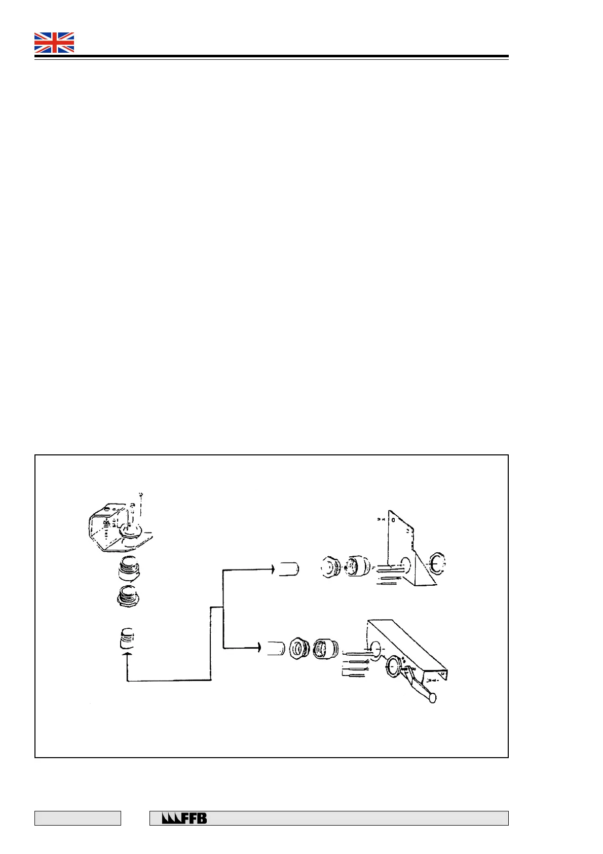
Fitting the hydraulic hose and electrical connections - 493 9031
• Connect the high pressure hose onto the auxiliary lifting ram in the adjustable track. The oil
return hose must be attached as soon as the auxiliary unit is mounted in position.
• Route the hoses into the chain and secure the chain along the cross-member using two M6 x 16
screws with serrated washers. Fit the angle bracket using two M8 x 16 screws with serrated
lock washers.
• Fit the inversion valve angle bracket onto the track using three M8 x 16 screws with serrated
lock washers.
• Connect the conduit and glands onto these two angle brackets.
• Connect the electrical cables into the junction boxes on the cross-members.
• Connect the HP hoses according to Fig. 11.
• Thread the HP and oil return hoses together with the electrical cable into the conduit and
connect them onto the power-pack.
• Fit the conduit angle bracket onto the power-pack using one M8 x 16 screw with serrated lock
washers.
• Connect the electrical cables onto the control panel.
• Check the settings of the circuit breaker are as follows:
6.3 A for 400 V
10 A for 230 V
Fig. 11
LIFT 493 9021
LIFT 493 9031