E 167 - GB - 6
24
Rue du Pré Neuf - 58440 MYENNES FRANCE
QUADRA
493 9021
493 9031
Thread torque
• The inside screws of the banjo connector must be tightened to a torque of 3 to 4 m/kg.
• Whenever the parts are re-assembled, it is important to always replace the copper seals.
LOWERING THE PLATFORM without electrical power
If the electrical supply has been interrupted, it is still possible to lower the platform by proceeding as follows:
• Remove the upper and lower covers on the vertical cross-member cheek plates.
• Raise one cross-member end with a crane or a jack until it is possible to manually extract the latch
from the ladder slot.
• Use steel wire to keep the latch retracted. Raise the sensing roller in order to unlock the cam (check
it) and whilst keeping it raised, re-lower the cross-member end. Repeat this procedure for the other
cross-member ends.
• Operate the ‘LOWER’ lever moderately so as not to cause the safety valve to function again.
CAUTION: STOP LOWERING THE PLATFORM IMMEDIATELY IF A CROSS-MEMBER
END, STOPS MOVING BECAUSE THE SAFETY BRAKE CAM HAS OPERATED.
If the safety brake cam of one of the cross-member ends is actuated, lift the end using a shop crane or a jack,
and then manually lift the wire rope sensing roller. Unlock the cam and lower the cross-member whilst keeping
the sensing roller raised. As soon as the platform reaches the ground, drive the vehicle off and at each end of
the cross-member, release the latches and re-fit the cheek plate covers.
RAM SAFETY VALVE
This valve is located in the hydraulic supply in the base of each of the rams. Should the supply hose rupture,
the valve stops the platform from being lowered by trapping the oil in the ram.
NOTE: If the valve in the slave ram is operated (in the right-hand track), the solenoid valve causes the left-
hand track to be brought to rest (this solenoid is controlled by the photoelectric control sensor).
Before replacing this valve, check the following:
• Poor adjustment of the flow rate controller causing the platform being lowered too quickly.
• An incorrect grade of oil has been used.
Check and adjustments
• Raise the platform half-way.
• Unscrew the hose and its connector see following warning.
WARNING: CARE SHOULD BE TAKEN DUE TO THE RESIDUAL OIL PRESSURE
IN THE RAMS. THE APPROPRIATE PERSONAL PROTECTIVE EQUIPMENT E.G.
GLOVES AND GOGGLES SHOULD BE WORN.
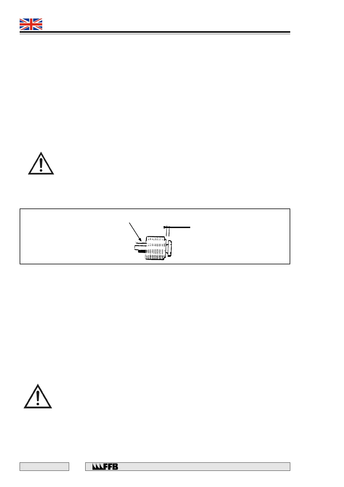
• Unscrew the valve using a special tool (Ref. 150031).
• Check that the clearance is 0.5 mm. If necessary, adjust the nuts to obtain this clearance (Fig. 16).
• Replace the valve in the ram, screw it in fully and then re-fit the hose and its connector.
Fig. 16
0.5 mm
Adjusting
nuts