20
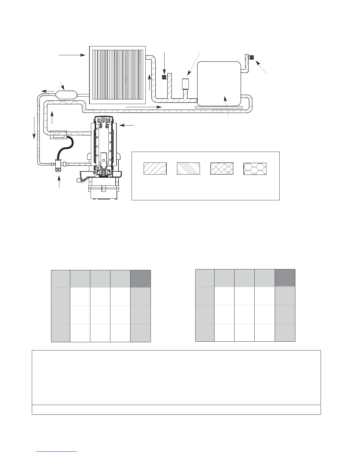
condenser
filter dryer
thermostatic
expansion
valve
evaporator
high side
service port
low side
service port
high pressure
switch
compressor
high
pressure
vapor
low
pressure
vapor
high
pressure
liquid
low
pressure
liquid
Technical speci cations (all models)
Refrigeration system diagram
Refrigeration pressure data
Notes: 1) Water regulating valve is factory set at 225 PSIG head pressure.
2) Readings within 10% of above table values should be considered normal.
Ambient air temperature ˚F/˚C
Ice machine inlet water temperature ˚F/˚C
°C,°@
50/10
70/21
90/32
60/16
174/23
174/23
190/25
80/27
245/31
244/30
265/32
100/38
237/37
326/38
347/40
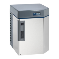
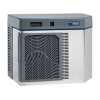
Air-cooled Ice machine
Refrigeration Pressure
Discharge Pressure/Suction Pressure
psi
psi
psi
Condenser inlet water temperature ˚F/˚C
Ice machine inlet water temperature ˚F/˚C
˚F/˚C
50/10
70/21
90/32
Water-cooled Ice machine
Refrigeration Pressure
Discharge Pressure/Suction Pressure
50/10
236/28
237/28
236/28
70/21
235/29
230/30
235/30
90/32
250/34
250/34
250/34
psi
psi
psi
Compressor data
Compressor current draw
Air-cooled
Ambient air temp. 60 F/15.6 C 70 F/21.1 C 80 F/26.7 C 90 F/32.2 C 100 F/37.8 C
6.3A 6.5A 6.7A 6.9A 7.1A
Water-cooled
Water temp. at oat 50 F/10 C 60 F/15.6 C 70 F/21.1 C 80 F/26.7 C 90 F/32.2 C
6.6A 6.7A 6.7A 6.8A 6.9A
Locked rotor amps 58.8