21
Gearmotor data
Gearmotor current 2.25A (nominal)
Locked rotor amps 14A
Ambient Air Temperature ˚F/˚C
Inlet Water Temperature ˚F/˚C
F
C
50
10
60
16
70
21
80
27
90
32
60
16
510
232
482
219
454
206
424
193
394
179
70
21
454
206
435
198
417
190
385
175
354
161
80
27
397
180
389
177
380
173
347
158
313
142
90
32
335
152
329
150
323
147
297
135
270
123
100
38
273
124
270
123
266
121
247
112
227
103
lbs.
kg.
lbs.
kg.
lbs.
kg.
lbs.
kg.
lbs.
kg.
Air-cooled ice machine capacity/24 hrs.
Ambient Air Temperature ˚F/˚C
Inlet Water Temperature ˚F/˚C
F
C
50
10
60
16
70
21
80
27
90
32
60
16
451
204
423
192
394
179
371
168
352
160
70
21
447
202
413
187
390
177
361
163
342
155
80
27
442
200
409
185
380
172
352
160
333
151
90
32
437
199
399
181
371
168
342
155
323
146
100
38
428
194
394
179
361
163
333
151
309
140
lbs.
kg.
lbs.
kg.
lbs.
kg.
lbs.
kg.
lbs.
kg.
Water-cooled ice machine capacity/24 hrs.
Performance with new RG Group 1/2 ton coil
(Note: Data expressed in lbs/hr and kg/hr)
Note: Nominal values – actual production may vary by ± 10%
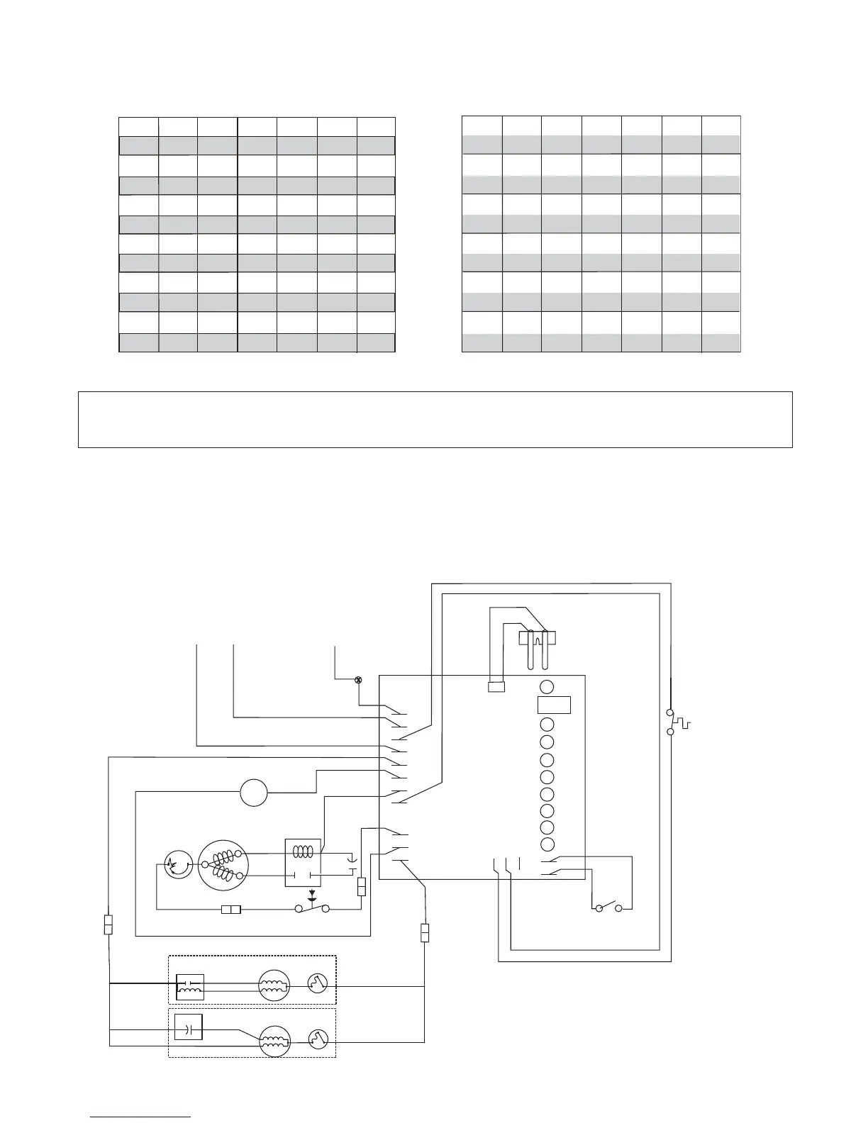
Electrical control system operation
MCD400A/WBT, MCD400A/WHT and MFD400A/WBT wiring diagram
Follett ice machines used on top of an ice storage bin have a slightly different circuitry. A diagram for these ice
machines is shown below. The operational and diagnostic stages for these ice machines will be otherwise the
same as the following stages 1 - 10.
M
GRD
L1
L1
L2
L2
L2
L2
L2
COMPRESSOR
FAN
DRIVE
DR
C
20M
60M
2ND
WTR
B-T
B-E
RESET
GRD
G
B
W
FAN
BLACK
WHITE
BLACK
BLACK
R
ORANGE
S
S
L
COMPRESSOR
C
RED
BLACK
BLACK
WHITE
INPUT
POWER
WATER
SENSOR
CONTROL
BOARD
BLACK
24V
COMMON
LINE VAC
RED
RED
WHITE
BLACK
BIN T-STAT
BIN SIGNAL
FROM DISPENSER
JUNCTION BOX
WHITE
RED
WHITE
M
1
COMPRESSOR
SWITCH
PWR
BLACK
T.O.L.
BLACK
RED
HIGH PRESSURE
SAFETY SWITCH
BLUE
RELAY
START
T.O.L.
BLACK
4
2
3
YELLOW
GEAR MOTOR
T.O.L.
GEAR MOTOR
BISON GEARMOTOR
RED
START
RUN
RUN
START
START CAP.
LINIX GEARMOTOR
OR