22
Electrical control system operation
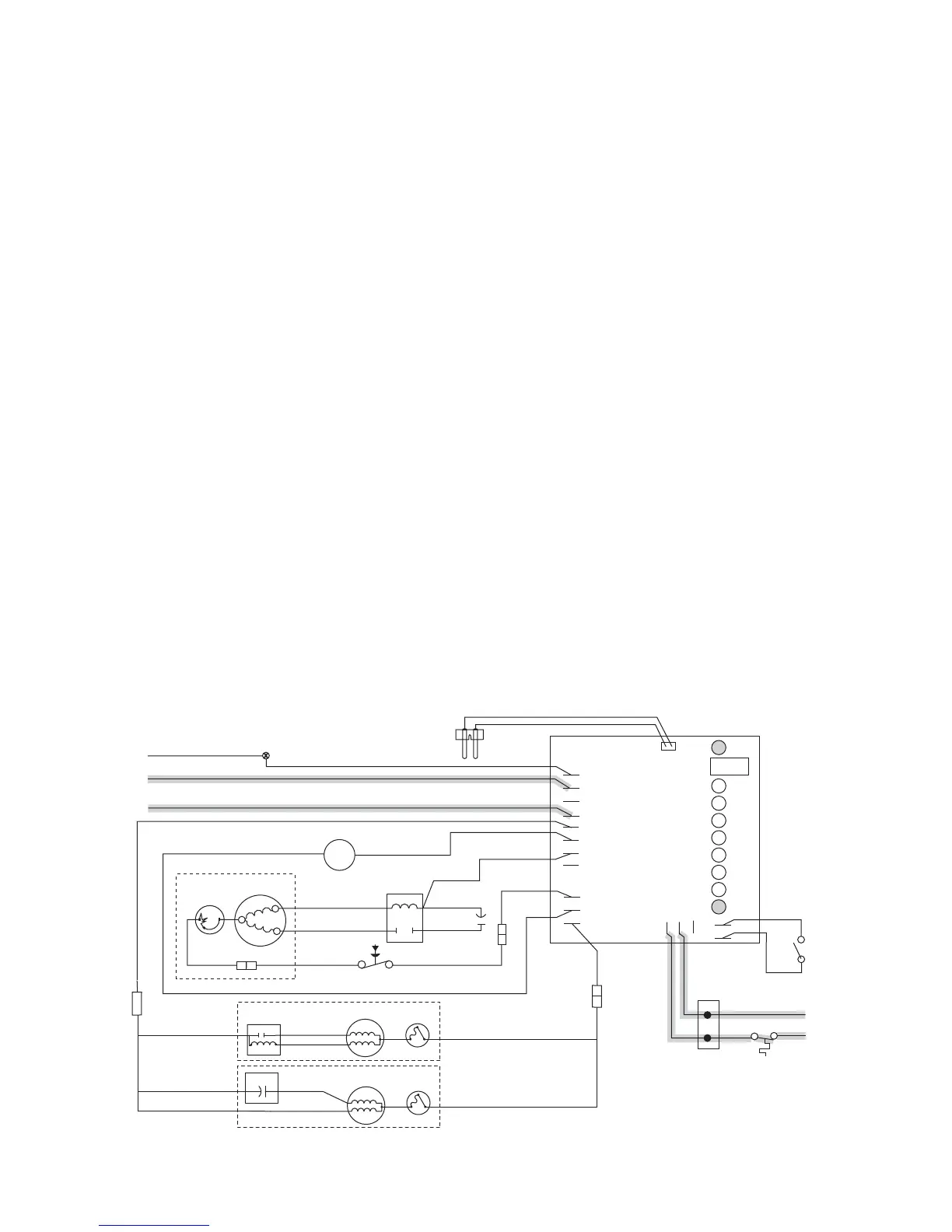
The D400A/W, MCD400A/WVS and R400A/W wiring diagrams which follow illustrate the circuitry of Follett ice
machines used with ice dispensers. Both normal operation of the ice machine (Stages 1 - 6) and non-normal
diagnostic sequences showing torque-out (Stages 7 - 10) for use in troubleshooting ice machine problems are
shown.
Follett ice machines used on top of an ice storage bin have a slightly different circuitry. The operational and
diagnostic stages for these ice machines will be otherwise the same as Stages 1 - 10 that follow.
Circuitry notes
When the ice machine is used with a dispenser it receives power from two sources – the main power supply and
the bin control signal power from the dispenser. Disconnect both power sources before performing service. When
performing electrical service, always use a meter to determine whether or not the components being serviced are
energized.
High pressure cutout opens at 425 PSI and closes at 287 PSI (auto reset).
Compressor switch should read open in on position.
Compressor start relay is position sensitive. See label on start relay for proper orientation.
Bin signal may be 120V, 60Hz; 230V, 50Hz; or 24V, 60Hz. If bin signal is 24V, 60Hz, black bin signal wire must be
moved from LINE VAC terminal to 24V terminal.
Flashing water LED at any time indicates that water signal to board had been lost for more than
one second.
Ten-second delay: There is a 10 second delay in reaction to loss of water (WTR) or bin (B-E) signals. If signals
are not lost for more than 10 seconds, no reaction will occur.
GRD
L1
L1
L2
L2
L2
L2
L2
COMPRESSOR
FAN
DRIVE
DR
C
20M
60M
2ND
WTR
B-T
B-E
RESET
GRD
G
B
W
FAN
BLACK
WHITE
BLACK
BLACK
R
ORANGE
S
S
L
COMPRESSOR
C
RED
BLACK
BLACK
WHITE
INPUT
POWER
WATER
SENSOR
CONTROL
BOARD
BLACK
24V
COMMON
LINE VAC
RED
RED
WHITE
BLACK
BIN T-STAT
BIN SIGNAL
FROM DISPENSER
JUNCTION BOX
(MCD400A/WVS series –
blk wire is on 24V)
WHITE
RED
WHITE
M
1
COMPRESSOR
SWITCH
PWR
BLACK
T.O.L.
BLACK
RED
HIGH PRESSURE
SAFETY SWITCH
M
BLUE
RELAY
START
T.O.L.
BLACK
4
2
3
YELLOW
GEAR MOTOR
T.O.L.
GEAR MOTOR
RED
START
RUN
RUN
START
START CAP.
WHITE
BISON GEARMOTOR
LINIX GEARMOTOR
OR
Normal operation – Stage 1
Power is supplied to L1 of the control board. The ice level control in the dispenser is closed and calling for ice,
supplying signal voltage to the control board. The control board will now go through the start-up sequence. Less
than 30 seconds will elapse as the water sensor located in the oat reservoir checks for water in the reservoir.
The Bin Empty LED (B-E) will be on.