12
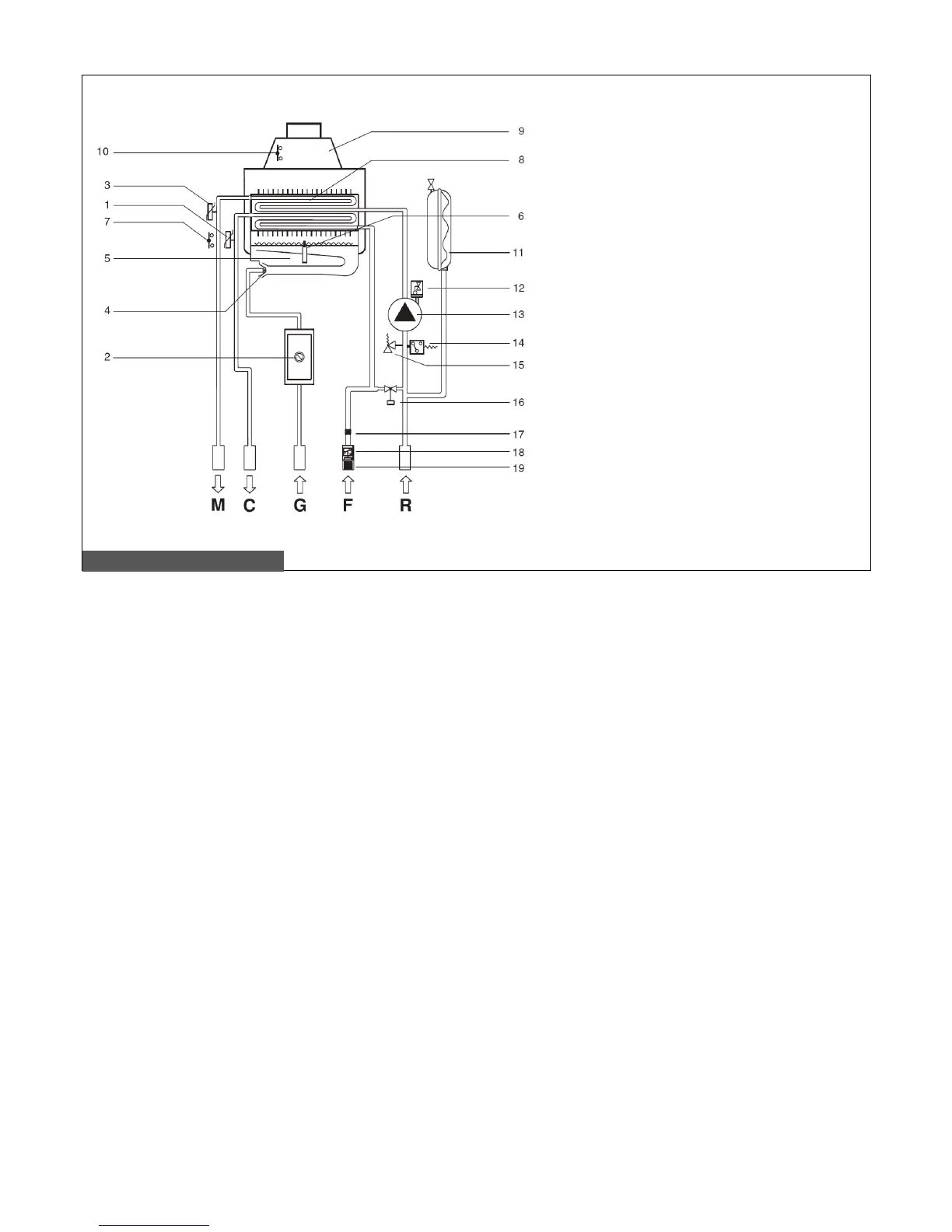
2.3 Hydraulic layout
Pic. 4 – Hydraulic layout
1. DHW temperature probe
2. Modulating gas valve
3. CH temperature probe
4. Burner nozzles
5. Burner
6. Ignition/flame sensing electrode
7. Safety thermostat
8. Bi-thermal heat exchanger
9. Flue gas hood
10. Flue gas thermostat
11. Expansion vessel
12. Air purging device
13. Pump
14. Water pressure switch
15. 3 bar safety valve
16. Loading tap
17. DHW flow limiting device – 10 liter per
minute
18. Domestic cold water flow switch
19. Domestic cold water inlet filter
M CH flow
C DHW flow
G Gas intake
F Water mains inlet
R CH return