23
3.6.
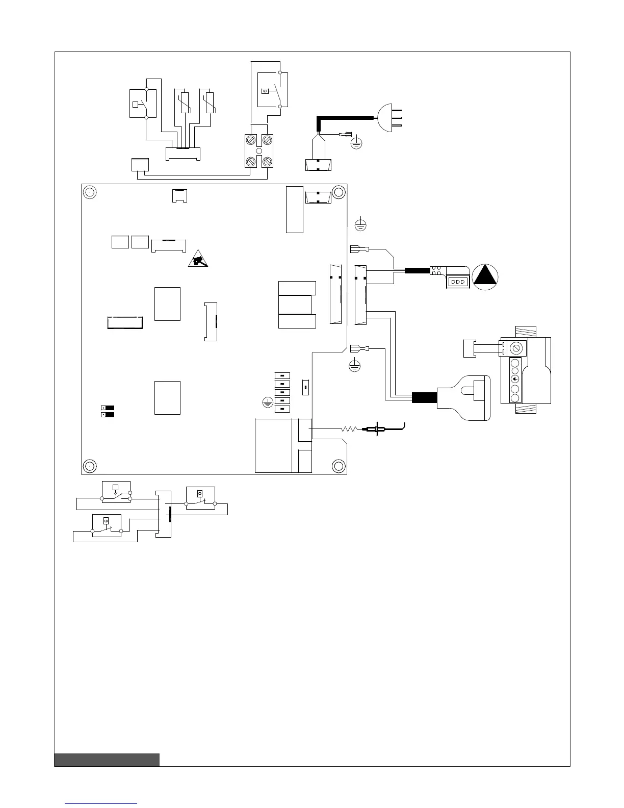
Pic. 10 – Wiring diagram
DK Low water pressure switch
SR NTC CH probe 10 Ohm at 25°C B = 3435
SS NTC DHW probe 10 Ohm at 25°C B = 3435
FL Flow sensor
VG Gas valve
TL Limit thermostat
E Detection/ignition electrode
P Circulation pump
TA Ambient thermostat (option)
TF Flue gas thermostat
CM1-CM2 Boiler type and gas type selection jumpers
2AF
9
A---B
M16
M15
RLPO1
RLVE1
RLGA1
PF1
M7
17
25
26
18
19
21
20
22
23
24
M8
10
11
12
13
14
15
16
M11
M9
M10
M1
1 2
3
M2
4
5
6
7
8
M6
M4
M5
M3
M14
M1
1 2
3
M2
4
5
6
7
8
N
N
1 4
5
M10
23
24
VG
N
2
E
SS
17
18
19
21
20
22
M9
SR
F
FL
25
26
M11
TA
M8
10
11
12
13
14
15
16
TL
NO
DK
C
P
NC
TF
P1
P2
CM2
CM1
CTN CTFS
CH4 GPL
M13
M16
M15
27
28
M12
M6
230Vac
50Hz
M4
P
M5