REAR PANEL
1.- 100-240 V AC power supply.
2.- Ethernet port. RJ-45 connector.
3.- RC-NET IN/LINK: input/output for interconnection of several MPX-4088 devices. Connect the LINK
output to the IN input of the next matrix and so on with the rest of the matrices up to a maximum of 16
matrices, 192 inputs and 192 zones. The matrices are configured using the PC software. RJ-45
connector.
4.- RD 9/10 - 11/12: ports corresponding to the digital input and output channels, 9/10 and 11/12. They
allow the connection of models MPX-400MIC, MPX-410ES, MPX-420V, MPX-430VS for sending and
receiving of control and digital audio signals. RJ-45 connector.
5.- RELAY: contact closures that can be controlled individually using PC software. They can be used as
switches for other electric devices. Euroblock terminals.
6.- INPUT/OUTPUT (1-8): balanced analogue audio input/output euroblock terminals. 48 V phantom power
supply available via PC software.
7.- FUSE: AC power supply protective fuse.
8.- LAN/RC-NET: allows the type of communication to be selected in the LAN port (2) between, TCP/IP in
LAN position or RS-485 in RC-NET position.
9.- RS-232: euroblock terminals to control via the series port.
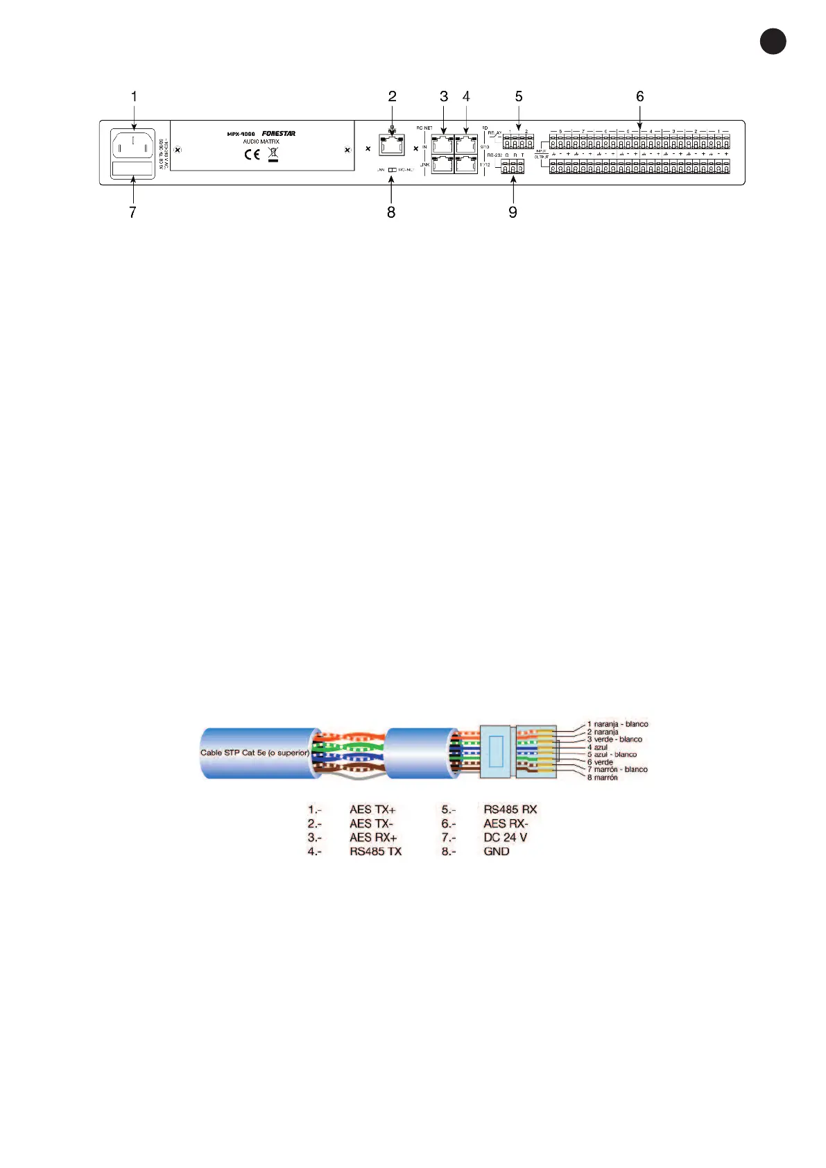
STP CABLE FOR RD PORTS
The RD ports transmit and receive AES3 Plus control signals. Below, the PIN-OUT is shown for an RJ-45
connector and STP cable.
Note: do not connect an RD port to a router, the router could be damaged.
- 5-
E
N