Option 1–System is mounted in a Vehicle
Option 2
–
System is mounted in a Static Location such as a bus
station monitoring system, site security system, etc.
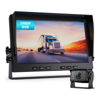
4.2.5 Option 1–Vehicle Power Installation
The power supply is normally a storage battery (9-36 Volts).
Connect the Yellow wire to the (+) positive terminal.
Connect the Black wire to the (–) negative terminal.
Connect the Red wire to the vehicle ignition
“
ACC
”
switch,
which is the gear switch setting in the ignition that is
immediately before the vehicle’s starter motor switch setting.
With this connection when the vehicle key is turned on, the
monitor will start automatically, and turn-off automatically when
the vehicle key is turned off.
Define which rear view camera will be the back-up camera in
your camera channel (CH) layout. For example, if you have
decided that it will be the CH2 camera to conform to your
preferred CH organization of screens that will be displayed on your
monitor; then connect the Green trigger wire (CH2 trigger) to the
vehicle’s reversing light. This configuration will automatically
display the CH2 camera on the screen whenever the vehicle is in
reverse gear.
You can connect the trigger wire according your need, or ignore them.
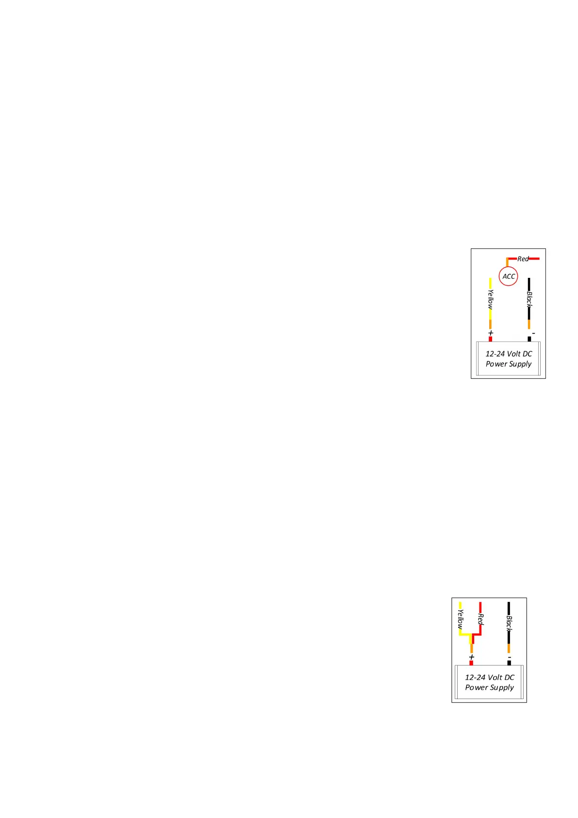
4.2.6 Option 2
–
Static Power Installation
Strip the end wires of the Yellow and Red wires.
Twist the end wires together.
Connect Yellow and Red joined wires to the (+) positive
terminal of the power source (9-36V).
Connect Black wire to the (-) negative ground terminal.
Ignore the trigger wire, unless there is a particular useful
application for them in your camera deployment.