20 01-28004-0028-20040830 Fortinet Inc.
Rear panel features Getting started
Rear panel features
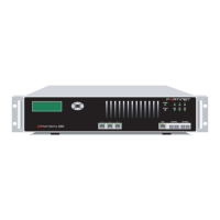
The FortiGate-4000 chassis rear panel contains and provides access to 4 cooling fan
trays, 7 power supply modules, 3 power supply connectors, the management module,
and the 10/100 out of band management module. The rear panel also contains:
• The internal and external ethernet pass-through interface modules
(FortiGate-4000P),
• The internal and external ethernet switched interface modules (FortiGate-4000S).
Figure 6: FortiGate-4000P rear panel
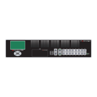
Table 4: KVM switch module front panel buttons
Button Description
FortiBlade select buttons Use these buttons to switch console access to each
FortiBlade-4010 module.
Table 5: KVM switch module front panel LEDs
LED State Description
ALARM Off Normal operation.
Red FortiGate-4000
unit power fault resulting from a failed power supply.
KVM Green KVM switch module is powered on.
LAN 9LAN 10 LAN 8 LAN 7 LAN 6 LAN 5 LAN 4 LAN 3 LAN 2 LAN 1 LAN 9LAN 10 LAN 8 LAN 7 LAN 6 LAN 5 LAN 4 LAN 3 LAN 2 LAN 1
LAN 2LAN 1
ONON OFFOFF
ERRERR
Management
module
Internal ethernet
pass-through
interface module
Cooling fan trays
Power
connectors
Chassis
Power
switch
Power supply
modules (7)
Power switch
Power on LED
Fan housing
Locking handle
External etherne
pass-through
interface module
10/100 out of ba
management
module
 Loading...